BALDER, Vlaardingen Herring Lugger from 1912, scratch build scale 1:50 Plate-On-Frame

I wish I could see the model 'in real'! This is just a fine example of how someone's wishes may become true! Do you plan to take a trip to New York? Take your time, there is no rush. The later you go with the model you will build! ;)
You can stay with us...
 
"The shape of the hull is becoming increasingly clear:"...and beautiful/amazing/delicate/precise/intricate!

I added some adjectives to your understatement about this incredible work.

Your patience and talent have me in awe!! Thanks for sharing such a great build log with the rest of us mere mortals.
 
I can now give me an estimate of how small it is once again all. And then positioning those half-curved beams a job where you hold your breath. I don't see any attachment you used for positioning so offhand, which makes it extra clever what you do.
 
A look at the production process:
The 4 half frames with reverse frames bent into shape on the Fushion prints:
View attachment 446095

The knee plates with profile against the deck stringer plates:
View attachment 446096

The half frames were first aligned at the bottom and secured between the keel and the keelson:
View attachment 446097
Then on the bilge profile and at the top against the knee plate.

The shape of the hull is becoming increasingly clear:
View attachment 446098
On to the remaining 4 half frames on the port side.
Regards, Peter
Good afternoon Peter. This project is a one of a kind build from someone with a unique skill set. Cheers Grant
 
I wish I could see the model 'in real'! This is just a fine example of how someone's wishes may become true! Do you plan to take a trip to New York? Take your time, there is no rush. The later you go with the model you will build! ;)
You can stay with us...
What a compliment and invitation, Jim. But traveling with a ship model (in a plane)? Here in the Netherlands we have a tv-serie 'Travel with a Goat". But till now they never got a plane ....... ;)
But you never know how we met each other some day. :)
Regards, Peter
 
"The shape of the hull is becoming increasingly clear:"...and beautiful/amazing/delicate/precise/intricate!

I added some adjectives to your understatement about this incredible work.

Your patience and talent have me in awe!! Thanks for sharing such a great build log with the rest of us mere mortals.
Hi Brad. You also thank you very much for this compliment. I never thought in August 2023 that this was the result (till now).
Regards, Peter
 
I can now give me an estimate of how small it is once again all. And then positioning those half-curved beams a job where you hold your breath. I don't see any attachment you used for positioning so offhand, which makes it extra clever what you do.
Thank you again for the compliments, Stephan. And the substantive response.
I mainly use 2 tools for alignment. But then I have to explain the way of working a little further.

First there is the construction floor that rises 1.5 degrees from back to front:
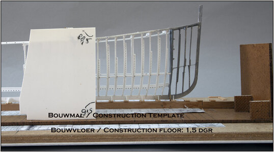
0234 1-5 dgr.jpg
On the construction floor I always use my 2 construction templates. This can be seen better in the 3rd (overview photo).
To get the frames perpendicular to the waterline, I made this angled mold. Placed behind a frame, I use the 91.5 degree angle. If that doesn't work in terms of position, I tilt the mold a quarter to the right and use the 88.5 degree angle. In both cases the 1.5 degree is compensated.

The frames and deck beams are perpendicular to the longitudinal direction. But I build the model in 2 halves.
I can tilt each half with its own construction template a quarter turn. It is then placed half on its center side.
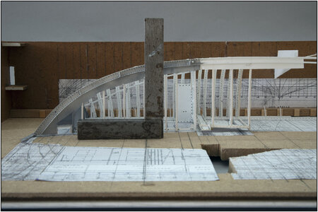
0235 Gekanteld.jpg
Then I use a 90 degree square to align perpendicularly.
The installation of the frames then continues 'by eye'.

Because I'm building 2 separate halves, both have to be aligned:
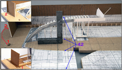
0236 Overzicht.jpg
That's why I pasted copies of the old drawings on the construction floor and both templates. All 4 on the same scale and aligned with each other on the frames. The blue arrows point to the 4 positions of frame 42.
To always build in the same position, I placed some ridges on the construction floor. Both construction templates always fall into those.
In the upright position, both templates fall into and over ridge 1, in the front and the back. See insert bottom left. Both templates aligned on the middle line.
In the tilted position the templates fall into the cams 2, see insert above left. But they are lying with the bottom plate in a angle of 1,5 dgr downwards from bow to stern. Otherwise the frames are not in 90 dgr.
Yes, a lot of math ....... ;)
Placing the frames is therefore always done 'by eye' with alignment on the drawings and both aids.
Hopefully I explained it clearly. It took me ‘some time’ to think of this, develop it and align it. :rolleyes:
Regards, Peter
 
Last edited:
Back
Top