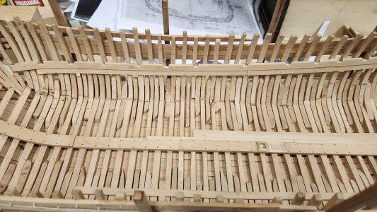
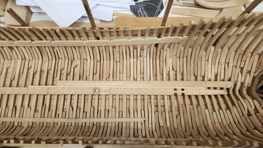
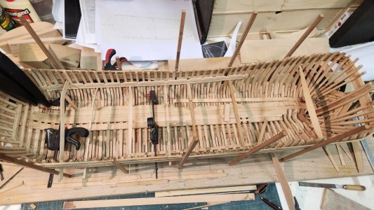
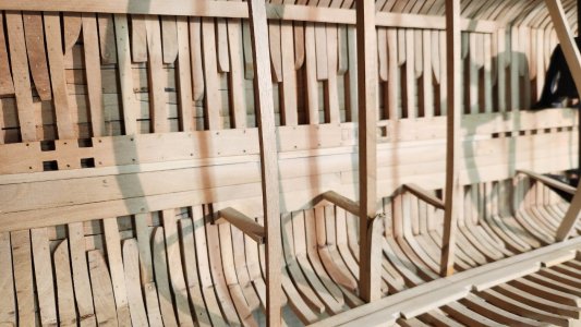
Until retirement in some 15 years this is the only time you can relax and carve, so until that time maybe no SOTSNice outside pictures of a nice inside view, Maarten. Good idea to do the carving during the holidays.
Regards, Peter

 |
As a way to introduce our brass coins to the community, we will raffle off a free coin during the month of August. Follow link ABOVE for instructions for entering. |
 |
 |
The beloved Ships in Scale Magazine is back and charting a new course for 2026! Discover new skills, new techniques, and new inspirations in every issue. NOTE THAT OUR FIRST ISSUE WILL BE JAN/FEB 2026 |
 |
Until retirement in some 15 years this is the only time you can relax and carve, so until that time maybe no SOTSNice outside pictures of a nice inside view, Maarten. Good idea to do the carving during the holidays.
Regards, Peter


Dear MaartenThe carving is put aside again for the next holiday afyer only some minor things have been added. The initials and some first scales were added.
View attachment 532470View attachment 532471
Back to the build with fairing the hull on the inside to fit the ceiling or wegering in Dutch.
After the use of the proxxon grinder with sanding disk doing the course sanding it is time for some elbow grease.
View attachment 532472
I use foam strips to which I glue some sanding linnen in grade 100 and 220. Which gives a perfect result in all the curved shapes.
View attachment 532473
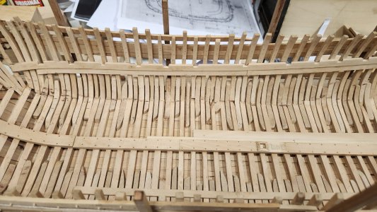
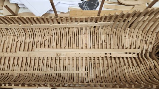
Now the inside is faired I can start measurements for the deck clamp, balkweger in Dutch, of the tween deck or koebrug dek in Dutch.
View attachment 532474View attachment 532475
Thx Shota.Dear Maarten
it's wonderful carving, and the hull of the ship looks beautiful


Nice construction details, Maarten. With a good fit on the inside sanded ‘oplangen’.Thx Shota.
The next step in the building is preparing the deck clamps for the koebrug deck.
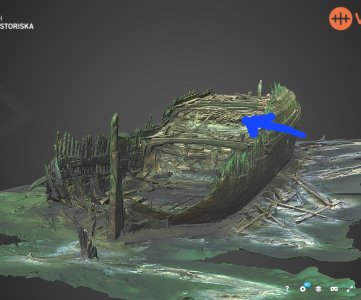
Normally a koebrug in a large ship is a light constructed deck to add dry cargo space to the ships hold and additionaly fitted to the orlop deck or overloop in Dutch. In the case of the fluyt it is the only tween deck and it does add to the overall strength of the ships hull. If I look at the wreck details of the Anna Maria fluyt where you can clearly see the koebrug deck and the top deck, called verdek you see a heavier construction on the koebrug then on the verdek.
View attachment 534518
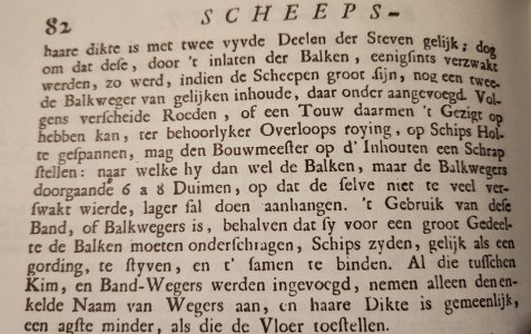
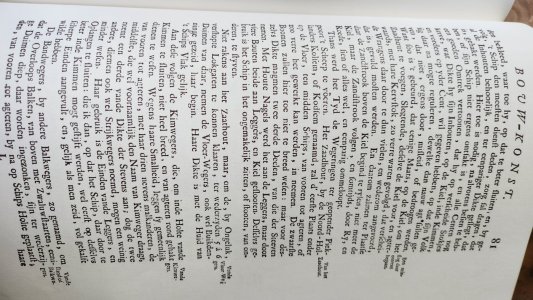
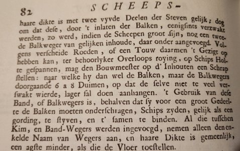
So I decided to also create a full size koebrug/overloop dek in my fluyt reconstruction. For the proportions of the deck clamps I refer to Van Yk.
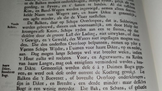
He states the thickness of the deck clamp is 2/5 of the thickness of the stempost.
View attachment 534519
View attachment 534520
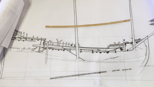
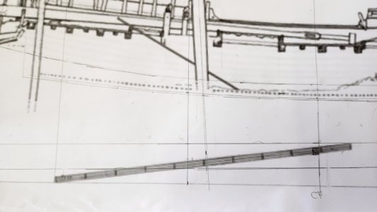
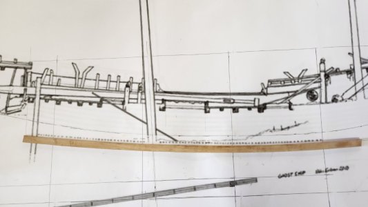
I use the archeological drawings for the curvature and placement of the deck clamps. In the build this was again done with a rope to create the deck curvature along the ships length.
View attachment 534669
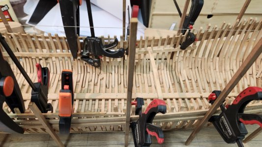
The height of the deck clamp is determined by the deck position as taken from the drawing, lowered with the curvature of the deck beams and the height of the deck beams above the deck clamp, which is half the thickness of the beam as these are counter sunk into the deck clamp with a dove tail connection. To add additional strength a second deck clamp was fitted below the one with the dovetails.
View attachment 534670
Showing these position of the deck clamp.
View attachment 534671
Finally fitting the deck clamps in position. The dove tails for the deckbeams already in place.
I have copied the beam positions from the verdek above it as often the beams were in the same positions as determined by the location of the hatches.
View attachment 534672
View attachment 534673
Next time the deckbeams.
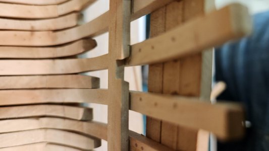
Ahh. I just realized you can't see the dovetail... Thanks, Maarten!Hi Paul,
In the deck clamp I made it with a Japanese saw and a chisel.
View attachment 534753
In the deck beams with a chisel.
View attachment 534751
View attachment 534752
So both by hand.

cheating with the bolt rope on the sails and now cheating with the dovetails...... We should look with an Indian eye to your build log...Ahh. I just realized you can't see the dovetail... Thanks, Maarten!
As far as you know I have no intention of cheating with the dovetailscheating with the bolt rope on the sails and now cheating with the dovetails...... We should look with an Indian eye to your build log...

You will follow the don't ask don't tell approachAs far as you know I have no intention of cheating with the dovetails

Ceiling planks!?! Don't tell me you are going to cover this Jenga stack of timbers!Next are the deck beams. Again using Van Yk for the dimensions and shape.
View attachment 534836
The thicknes of the beams is 2 inches per 5 feet ships width.
My ship is 25 feet wide which means the beam should be 10 inches or in Dutch 10 duimen which is to scale just above 7 mm. The width of the beam should be equal or more if the used wood allows, this also means the width of the beams can vary from beam to beam in the same ship.
The curvature of the beam is 6 to 7 inches.
Dry fitting the first beams into their dovetail slots.
View attachment 534837
View attachment 534838
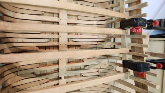
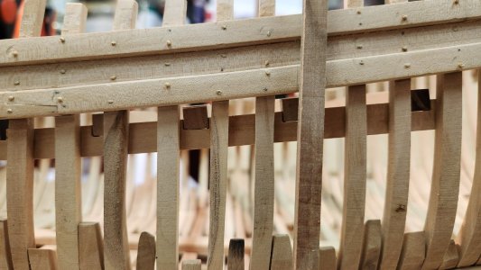
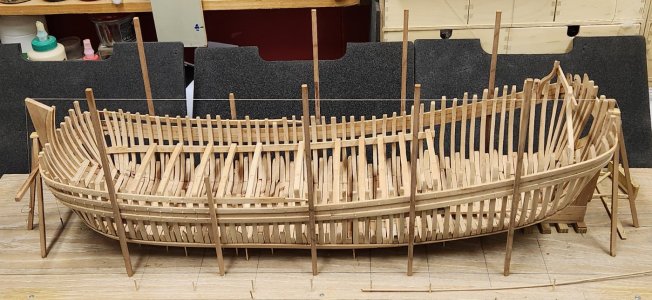
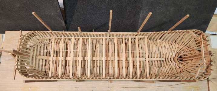
All the beams are made and temporary in place before removal to start on the ceiling planks.
View attachment 534841View attachment 534842
Before starting the ceiling I have to make a choice if I leave the hull open on 1 side or if I fully plank both sides.
Ideas are welcome as long there is no Japanese saw involved
Yea me too.I am in awe!
With such a beautiful construction, there is only one option: please leave one side open, Maarten.Before starting the ceiling I have to make a choice if I leave the hull open on 1 side or if I fully plank both sides.
Ideas are welcome as long there is no Japanese saw involved
