
-

SUBSCRIBE TO SHIPS IN SCALE TODAY!
The beloved Ships in Scale Magazine is back and charting a new course for 2026!
Discover new skills, new techniques, and new inspirations in every issue.
NOTE THAT OUR NEXT ISSUE WILL BE July/August 2026 -

Win a Free Custom Engraved Brass Coin!!!
As a way to introduce our brass coins to the community, we will raffle off a free coin during the month of August. Follow link ABOVE for instructions for entering.


You are using an out of date browser. It may not display this or other websites correctly.
You should upgrade or use an alternative browser.
You should upgrade or use an alternative browser.



Thanks for the compliment.
- Joined
- Jun 12, 2026
- Messages
- 13
- Points
- 8

Awesome build!!
Thanks

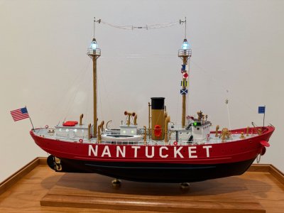
The LEDs come from: https://evandesigns.com/collections...uEmiNeNITOh2km6m5gh8aFdsx2tjMFjsaAojoEALw_wcBThis looks spectacular! Where did you get the lights from? Where is the battery pack hidden?
I recommend that you start out getting those from Evans. Once you play around with them a little bit and if you’re moderately good with electronics, and plan to do more LED projects in the future you can buy most of the components from Amazon and piece it all together yourself. I also bought from Evans a neat electronic foghorn which I placed the speaker for under the base. Initially, I had it blowing all the time, but my family complained about it so I put a switch on it and occasionally put it on when I show off the model.
If you plan to do navigation lights , you’ll have to get some small hollow brass fittings that allow for the insertion of the LEDs. The ones provided in the Blue Jacket kit are solid castings so you can’t put LEDs in them.
I don’t know if Evans has them, but I did buy some from Harbor models, https://www.harbormodels.com/lighting.html. I think they may also sell complete lighting kits.
I did not use a battery pack, but powered the lights from a plug-in, DC adapter. The tricky part was to get the power up from under the base into the ship cabins and up to the lights on top of the masts. The model has a solid hull so trying to place a battery pack in it would’ve involved a lot of removal of solid material from the hall to create a space. I thought that would be pretty messy and might have damaged the hull. Besides that I wasn’t crazy about the idea of having to constantly change the batteries out. Also, it eliminates the perennial problem of forgetting to changing batteries and then have them leak into a battery compartment. Also it allowed me to plug the power adapter into a timer which goes on at dusk and off at dawn using the lights from the model as a night light in the hallway of my house.
To get the power from under the base into the model, I utilized brass pedestals available from https://www.bluejacketinc.com/cases-pedestals-baseboards/
Each pedestal will carry separately each leg of the power circuit. Since LEDs have polarity, you need to keep track of which one will be positive and which negative. It’s a good idea to mark the underside of the base as to which hole is which plus or minus. To transmit the power to the bottom of the hull. I drilled a perpendicular hole using an extra-long specialty drill sized to allow a 5 mm brass tube to snuggly fit, from the bottom of the hull to the level of the deck. Using a mini-router such as available from Dremel or by carefully cutting and chiseling form a channel from where the holes exit into the deck to where the deck cabins and also the base of where the masts will be. The tube is cut to a length so it is flush to the bottom of the hull and extends about 1.5 inches into the hull. Insert a 9 inch cooper wire AWG 26 and solder it to the inside of the other side of the tube. Thread the wire into each hole from the bottom of the hull then position the tube so the unsoldered end is flush with the bottom of the hull and the wire protrudes out through the deck. Apply glue to the tubing. I ran thin CA done the side of the tubing but I think in the future I would use epoxy applied before insertion for better structural support. Run the wires to the cabins that you want to power and illuminate and the bases of the masts through ABS square plastic tubing such as this which can be placed into the previously constructed channels: https://www.amazon.com/dp/B0BWM4W2TS?ref_=ppx_hzsearch_conn_dt_b_fed_asin_title_7&th=1
Once the channels are placed, glue them down and then fill in with Tamiya wood putty and sand so they are flush and smooth with the deck.
When you are ready to mount the model to the pedestals you will be able to screw the pedestals right into the tubes where they exit the bottom of the hull. Therefore no additional holes in the hull for wires needed for power. The power adapter will be wired onto lugs mounted onto the pedestal mounting screws and the power transmitted through the screws to the brass tubing, to the soldered wire and then up to the deck level
To get the power up to the mast. Construct the masts out of hollow brass tubing of a similar diameter to the wooden masts supplied with the kit. I think I used 7mm diameter. Drill a small hole in the bottom of the mast positioning it so it will line up properly with the square channel that has been run up to the base of the mast. Use small gauge wire, 30 gauge, which I think which either comes with some of the LED kits or can be purchased from Evans to run through the channel to the hole in that was drilled in the side of the tube and up to the beacon lights on the top on the masts. I used 5mm diameter LEDs for those lights. If you wanted to get fancy you could build a circuit that would flash at a slow realistic rate, I did one that flashed at a 8 second period or just use one that is on all the time. Building that circuit board is a whole other project which I can’t get into here right now. You need to be an electronics hobbyist to do that. Make sure you prime and paint the brass tubing before mounting the LEDs. Don’t paint the bottom below the deck level of the tubes where they will be glued into the hull.
Make the roofs of the cabins removable because you will need to be soldering the wiring after they have all been painted and glued into place. You will probably have to install the ladders and stairs after the roofs are put back into place.
It was all a very fussy project but it was really worth the effort.