- Joined
- Oct 31, 2024
- Messages
- 21
- Points
- 28

Hello everyone
This is my first consultation, it is about something that is complicated for me, until now to make holes I had used a hot or cold punch, to enlarge an existing one, the fact is that it is about making a hole , so that you know better what I am talking about, I am attaching a series of screenshots, which I hope can help in some way:
The fact is that I have a model of the CSS Alabama, from Revell, a model that is difficult to find nowadays and that from what I have seen, reaches very high prices online, this is the 2006 edition, the hull and the textures are very well done, but the hull, as is usually something normal in revell, especially in large 1:96 scales, is a copy of the kearsarge, as also happens with the Cutty sark/thermophila/Pedro Nuñes or the case of the Bounty/Beagle, when adapting it, modifications are made so that it resembles the real model as closely as possible, in this case with a mechanism for raising or retracting the propeller, but the original mold did not have the gap, since the The original ship (the kearsarge) did not have this mechanism, and the ship represented (the Alabama) does have it, but Revell, using the same mold, did not make the hole by default.
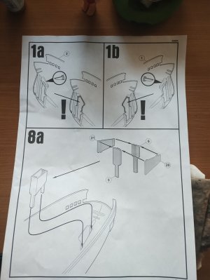
This is the screenshot of the instructions, it is the first step that must be taken, the fact is that the mold does not have the hole made in either of the two sections of the hull and it must be done.
This is how the propeller assembly would look from the inside, this is the propeller retraction mechanism, and the fork slides vertically through the propeller well.
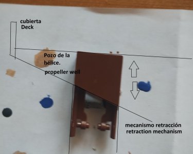
This is how the propeller assembly would look with its normal operating appearance in propeller navigation.
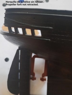
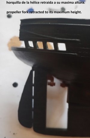
and this is how it would appear with its withdrawn appearance when sailing.
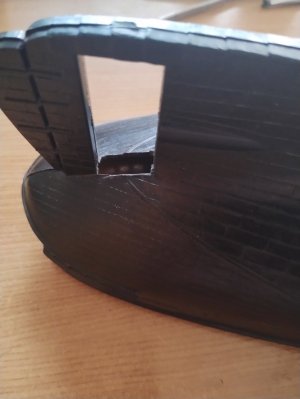
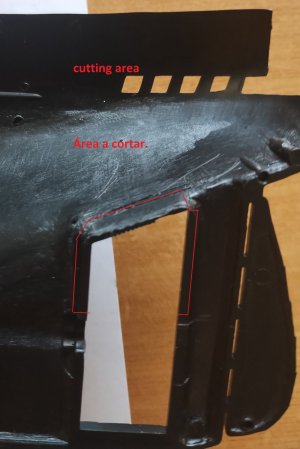
This screenshot shows one of the two halves of the hull and the area to be cut to fit the retraction mechanism.
I have found alternatives such as cutting the propeller fork frame and leaving it fixed, the operation would be like this:
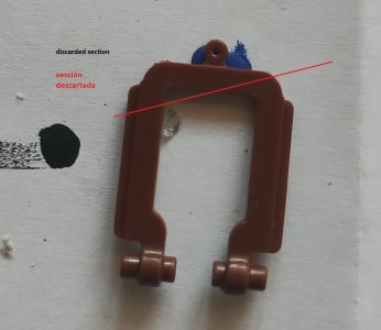
Here you can better see the discarded area, this would stick in the space of the propeller hole and remain fixed, without being able to retract, but simulating the mechanism in the navigation position. Regardless of how it is done, it has to be attached, or else the propeller will not be able to attach to the hull.
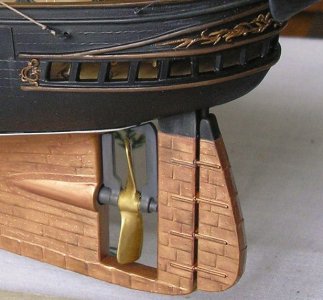
In this internet capture from a modelers forum you can see the solution that was adopted:
In any case, how could the hole be made? What tools would I need? I tried to cut it with a cutter, but I only managed to scratch it, the plastic is extraordinarily thick and I don't want to break it.
I don't know how to proceed, I've never had to do something like this and I don't want to break the plastic trying it without first asking how to make the hole, especially considering that it is a discontinued model and is not so easily found.
This is my first consultation, it is about something that is complicated for me, until now to make holes I had used a hot or cold punch, to enlarge an existing one, the fact is that it is about making a hole , so that you know better what I am talking about, I am attaching a series of screenshots, which I hope can help in some way:
The fact is that I have a model of the CSS Alabama, from Revell, a model that is difficult to find nowadays and that from what I have seen, reaches very high prices online, this is the 2006 edition, the hull and the textures are very well done, but the hull, as is usually something normal in revell, especially in large 1:96 scales, is a copy of the kearsarge, as also happens with the Cutty sark/thermophila/Pedro Nuñes or the case of the Bounty/Beagle, when adapting it, modifications are made so that it resembles the real model as closely as possible, in this case with a mechanism for raising or retracting the propeller, but the original mold did not have the gap, since the The original ship (the kearsarge) did not have this mechanism, and the ship represented (the Alabama) does have it, but Revell, using the same mold, did not make the hole by default.
This is the screenshot of the instructions, it is the first step that must be taken, the fact is that the mold does not have the hole made in either of the two sections of the hull and it must be done.

This is how the propeller assembly would look from the inside, this is the propeller retraction mechanism, and the fork slides vertically through the propeller well.

This is how the propeller assembly would look with its normal operating appearance in propeller navigation.

and this is how it would appear with its withdrawn appearance when sailing.

This screenshot shows one of the two halves of the hull and the area to be cut to fit the retraction mechanism.

I have found alternatives such as cutting the propeller fork frame and leaving it fixed, the operation would be like this:

Here you can better see the discarded area, this would stick in the space of the propeller hole and remain fixed, without being able to retract, but simulating the mechanism in the navigation position. Regardless of how it is done, it has to be attached, or else the propeller will not be able to attach to the hull.
In this internet capture from a modelers forum you can see the solution that was adopted:

In any case, how could the hole be made? What tools would I need? I tried to cut it with a cutter, but I only managed to scratch it, the plastic is extraordinarily thick and I don't want to break it.
I don't know how to proceed, I've never had to do something like this and I don't want to break the plastic trying it without first asking how to make the hole, especially considering that it is a discontinued model and is not so easily found.


