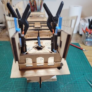
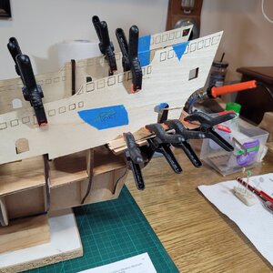
....some hints from my experience
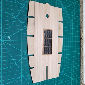
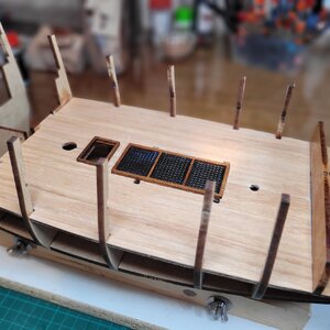
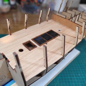
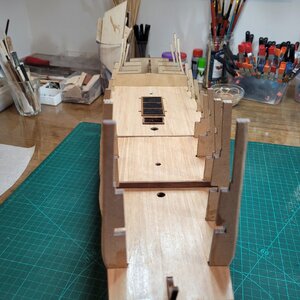
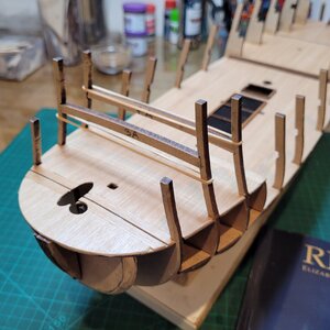
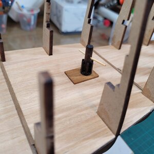
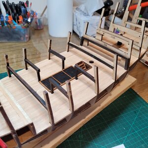
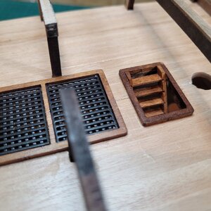
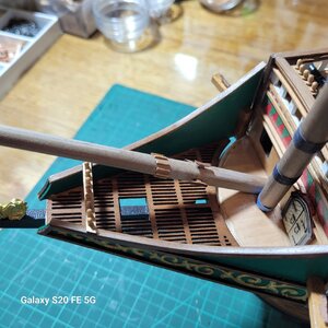
1. When fitting part 222 grating to part 50 forecastle deck, you need to use the one example of 222 which has a rectangular hole cut in it. The allows the samson post inside the forecastle to be reached for rigging. No way of knowing unless you happen to notice on the complete plan view towards the end of the book. First photo shows this.
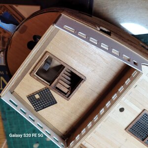
2. The aft edges of parts 21 need about 3mm of thickness added to meet the topsides nicely.
3. When gluing the decorations on the last long section at the wale is awkward to handle so I cut it in half so I could use four piecs rather than 2 and that was easier...not a major thing but the paper does get a bit awkward when wet.
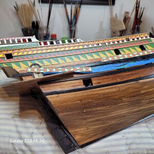
4. First serious issue....Bowsprit plans. ..(what follows is entiely my opinion and I could be completely off the mark..!)
(a) Plan 4 shows a representation of the bowsprit going into the hull...this is indicative only and the bowsprit cannot stop in midair where shown...it is drawn as 85mm into the hull from the deck surface when it needs to be 128mm to find its stopping point..
(b) the adjacent plan dawings for the bowsprit on plan 8 are not correct. If you make the bowsprit to the overall size specified and then fit the chocks and cleats where drawn the gammonning chocks will not be above the gammon slot in the prow, and the horn cleats will be underneath the forecastle. It is a moot point what is wrong...but you need to plan the bowsprit build and install yourself using the only two pieces of predetermined data you have....first the limit of the bowsprit insertion which is 128mm from where it first emerges from below the focsle, and second where the gammoning slot is in the prow. Put a small square upight on the bow grating at the gammon hole and mark the position of the gammon on your bowsprit.
(c) Then just put all the other horn cleats and stopper cleats approximately where the drawings show ignoring the fact that the plan view and side view have some in quite different locations.
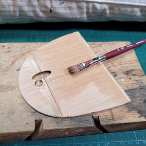
I had precut my bowsprit to length and given all the above it was now too short so I added a bit to the internal end giving it the correct "hidden" depth of 128mm.
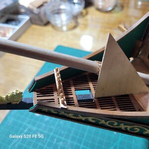
Ugly huh..? but hidden
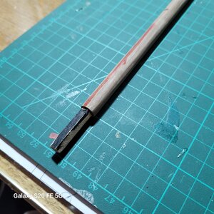
I hope I havent somehow missed something crucial and set people off on a wild goose chase because I find it very surprising to come to these conclusions... if I am right then it is the first time I have found a significant issue with Amati plans.
In the end I have my gammonning cleats above the gammon slot, and the horn cleats out where they can be used.... so I am happy with my end point just a bit nervous about how I got there.
PS...now that I have finished the bowsprit and the gammoning I can confirm my notes above...the plans are not right here... do your work with the gammon slot as your datum
5. Rigging the main foreyard haul. It rigs to a violin block ( see P6 of log) and to a samson post below the forecastle ( see point 1. picture of this post). It would save a lot of grief if you rigged this part of the yard haul between the violin block and the samson post before planking the foredeck. It can be done later as per plan 15 but it is very difficult and completely avoidable....The exact length is unimportant so rigging it very early is fine.
6 . Forecastle guns...the plans/instructions (I forget which) have you place the two forecastle guns in the second opening back from the front bulkhead . This ends up being behind a shroud...all other guns are good. Just position the focsl guns in the third opening not the second and it is pr=erfectly between the sets of shroudfs.
1. When fitting part 222 grating to part 50 forecastle deck, you need to use the one example of 222 which has a rectangular hole cut in it. The allows the samson post inside the forecastle to be reached for rigging. No way of knowing unless you happen to notice on the complete plan view towards the end of the book. First photo shows this.

2. The aft edges of parts 21 need about 3mm of thickness added to meet the topsides nicely.
3. When gluing the decorations on the last long section at the wale is awkward to handle so I cut it in half so I could use four piecs rather than 2 and that was easier...not a major thing but the paper does get a bit awkward when wet.

4. First serious issue....Bowsprit plans. ..(what follows is entiely my opinion and I could be completely off the mark..!)
(a) Plan 4 shows a representation of the bowsprit going into the hull...this is indicative only and the bowsprit cannot stop in midair where shown...it is drawn as 85mm into the hull from the deck surface when it needs to be 128mm to find its stopping point..
(b) the adjacent plan dawings for the bowsprit on plan 8 are not correct. If you make the bowsprit to the overall size specified and then fit the chocks and cleats where drawn the gammonning chocks will not be above the gammon slot in the prow, and the horn cleats will be underneath the forecastle. It is a moot point what is wrong...but you need to plan the bowsprit build and install yourself using the only two pieces of predetermined data you have....first the limit of the bowsprit insertion which is 128mm from where it first emerges from below the focsle, and second where the gammoning slot is in the prow. Put a small square upight on the bow grating at the gammon hole and mark the position of the gammon on your bowsprit.
(c) Then just put all the other horn cleats and stopper cleats approximately where the drawings show ignoring the fact that the plan view and side view have some in quite different locations.
I had precut my bowsprit to length and given all the above it was now too short so I added a bit to the internal end giving it the correct "hidden" depth of 128mm.


Ugly huh..? but hidden

I hope I havent somehow missed something crucial and set people off on a wild goose chase because I find it very surprising to come to these conclusions... if I am right then it is the first time I have found a significant issue with Amati plans.
In the end I have my gammonning cleats above the gammon slot, and the horn cleats out where they can be used.... so I am happy with my end point just a bit nervous about how I got there.
PS...now that I have finished the bowsprit and the gammoning I can confirm my notes above...the plans are not right here... do your work with the gammon slot as your datum
5. Rigging the main foreyard haul. It rigs to a violin block ( see P6 of log) and to a samson post below the forecastle ( see point 1. picture of this post). It would save a lot of grief if you rigged this part of the yard haul between the violin block and the samson post before planking the foredeck. It can be done later as per plan 15 but it is very difficult and completely avoidable....The exact length is unimportant so rigging it very early is fine.
6 . Forecastle guns...the plans/instructions (I forget which) have you place the two forecastle guns in the second opening back from the front bulkhead . This ends up being behind a shroud...all other guns are good. Just position the focsl guns in the third opening not the second and it is pr=erfectly between the sets of shroudfs.
Last edited:


