Ancient Phoenician Trade Boat 1500-1400 BC Build Log PT-2

Joined
Jul 2, 2020
Messages
4,110
Points
588

Location
Eugene, Oregon
Starting a somewhat redundant log from an earlier one that morphed into the Kyrenia model in it's own log.
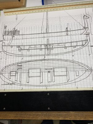
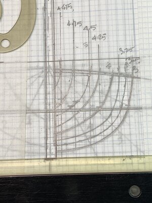
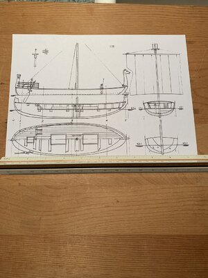
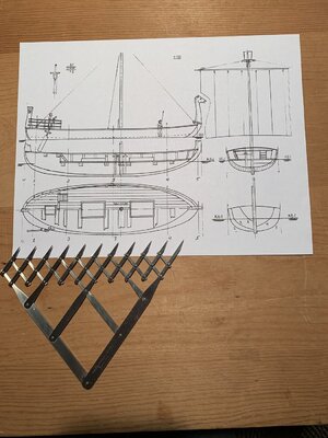
I will open with the photos of the single sheet that I will enlarge and work up the hull lines to create the mold/frames from there in this scratch build.
8.5x11 plan with engineering scale.jpg8.5 x 11 print of Trade Boat Plan Sheet with dividers.jpgHull Cut Lines for Mold Lines.jpg
With only this sparse information I will embark on a voyage into the foggy dew drifting atop the waves of the unknown, relying upon the research papers and Kyrenia model experience to amplify the voids. Rich (PT-2)
 
It seems like a daunting task. Will the majority of your drawing be on computer or paper? I know people are very computer savy but I am not so if it was me I'd use french curves for the individual frame lines.

Raymond
 
That looks like quite the project. I've pulled my chair closer to my PC and I am looking forward to following your log.

Jan
 
That looks like quite the project. I've pulled my chair closer to my PC and I am looking forward to following your log.

Jan
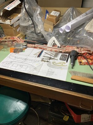
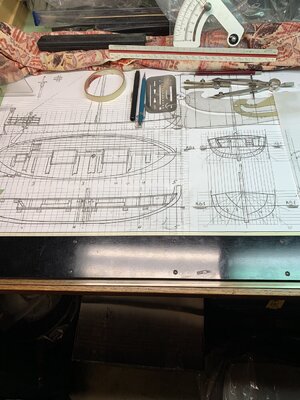
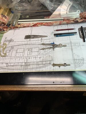
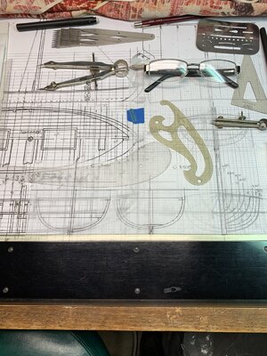
Not having a CAD program in my computer and only the enlarged plan from 8.5x11 to this larger size I am working in our unheated garage on my sacrificed drafting table: rear half has a covered row of mini wood working equipment and the front half for manual drafting which was for more that 2/3 of my architectural career. 39 Degrees unheated but interest in the voyage keeps the fingers just flexible. Here is the setup:
Trade Boat Drafting Table and Mini-Equipment Bench.jpg
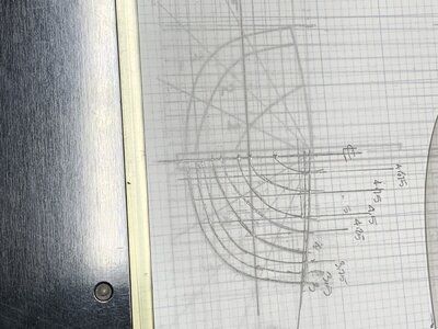
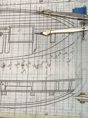
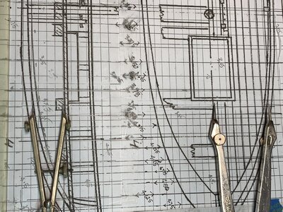
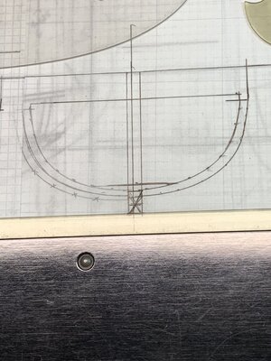
You have seen the paper doc on the prior post so I'll move in showing the lines taken off with dividers and the curves for joining the points:
Trade Boat Inital half Bow Sections.jpg
I don't know why my iPhone camera rotates the image but the parallel ruler on the left is the same as shown in the correct horizontal place on the table. A major problem with the plan sheet that was sent as a downloadable file is that lines in the four different drawings are not well aligned. I drew the matrix of grid lines to start with but at this point they are not needed, I also drew the offset diagonals as a crude means of checking what I take off from the plan and elevation using the plan centerline for horizontal and section drawing above for vertical offsets. My thought is to oversize all frames and when set in a strongback to do a lot of filing/fairing to smooth the faces to true strakes curves. This will be like wood sculpture as I see it with manual intervention guiding the course. Reverse forensic design to develop the skelaton sufficiently true to be a mold for the edge connected shell construction true to the Bronze Age shipbuilding procedure. (Same as the Kyrenia II hull and my model of that.)
Rich
 
This will be very interesting project.
and:
I am very happy to see a modeler with a working area looking similar to mine ;)
 
This will be very interesting project.
and:
I am very happy to see a modeler with a working area looking similar to mine ;)
My actual modeling are is inside the house in my warm but overloaded den with a board on top of the desk drawers pulled out. The garage is for larger cutting, sanding, lathe work, along with a small drill press and scroll saw. Cluttered wherever I look in both places. Rich
 
My actual modeling are is inside the house in my warm but overloaded den with a board on top of the desk drawers pulled out. The garage is for larger cutting, sanding, lathe work, along with a small drill press and scroll saw. Cluttered wherever I look in both places. Rich
Continuing to "lay the keel" of this boat I have been following my typical tack of my voyage to pull together as much related information and resources as feasible for study and personal incorporation into the project, departing from the impoverished plan sheet for a more comprehensive hull, spars, rigging, and sail to be crafted.

Two of the research resources at hand are in the following links to review if anyone is curious:


Most visual images online are only artists impressions that need to be challenged and vetted against available research papers and illustrations. Most of the online ships are of warships which are not suitable to exploration and general seafaring so I will not be following that tack but instead focus upon the ships of less attention whereby the Mediterranean was crossed in many ways of trade and exchange of cultures.
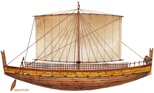
One good illustration culled out is attached:
Phoenecian Trade Ship Stbd Elev.gif
Immediately different to view is the presence of two yards and the rigging of the sail which is commonly seen in the ancient Egyptian vessels.

Like those old ships this will be a slow voyage and needing attention to the winds and storms arriving from across the horizon.
Rich (PT-2)
 
Oh man, Rich. That brings back memories seeing your electric eraser. When I moved from drafting table to CAD I still used my electric eraser with a little grit for engine turning finishes on metal.
 
Oh man, Rich. That brings back memories seeing your electric eraser. When I moved from drafting table to CAD I still used my electric eraser with a little grit for engine turning finishes on metal.
My drafting table is disassembled and in the storage shed. Still have the electric eraser and eraser shield. And still have lots of vellum. Brings back memories!
 
My drafting table is disassembled and in the storage shed. Still have the electric eraser and eraser shield. And still have lots of vellum. Brings back memories!
Yes, there is a faint aroma given out by the electric eraser and procedure which may linger if frequent erasing is needed . . . ideally seldom but that is not always the case. Good old rubber on velum was better for that than polydrafting on those (often overlay when pin-bar was used prior to the advent of CAD which has no feedback other than the explicatives when all of the work vanishes when not frequently saved. Large advanatage to manual drafting in that regard. Rich
 
Yes, there is a faint aroma given out by the electric eraser and procedure which may linger if frequent erasing is needed . . . ideally seldom but that is not always the case. Good old rubber on velum was better for that than polydrafting on those (often overlay when pin-bar was used prior to the advent of CAD which has no feedback other than the explicatives when all of the work vanishes when not frequently saved. Large advanatage to manual drafting in that regard. Rich
Looking back now at the photo of the drawing sheet I realize that the body plan and elevation need to be aligned with the hull section for better alignment of the frames to the keel left and right. Bad drawing layout on the sheet by a kit designer who was not familiar with the recommended arrangement. I don't trust making a large photo copy of the sheet as it is so I'll take the alternate risk of mis-alignment and cut the sheet to re-tape it in the proper manner (with some assisting guide lines). Rich
 
Looking back now at the photo of the drawing sheet I realize that the body plan and elevation need to be aligned with the hull section for better alignment of the frames to the keel left and right. Bad drawing layout on the sheet by a kit designer who was not familiar with the recommended arrangement. I don't trust making a large photo copy of the sheet as it is so I'll take the alternate risk of mis-alignment and cut the sheet to re-tape it in the proper manner (with some assisting guide lines). Rich
With some care for alignment, a sharp blade and metal straight edge I cut the plan sheet to move the body plan from left of the body plan and strakes lines, upwards and the shear plan elevation down to align horizontally with the body plan's lines.
Revised Plan Sheet 12.22.jpg
With this repositioning I will be better able to draw the frames/bulkheads for the hull mold planking with added notches inboard for longitudinal wales matching the gentle curve of the deck and deck beams.
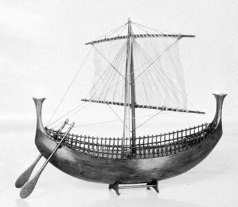
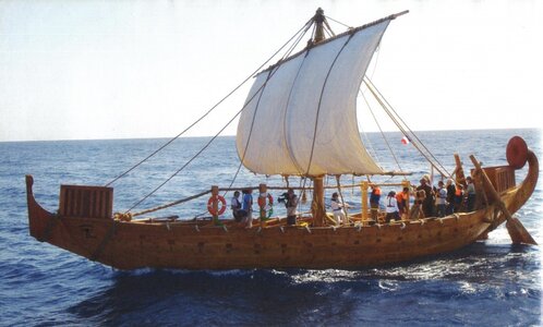
Aside from this I have surfed the net for the most inclusive and agreeable images of the yards and sail rigging. As the only known aspect of these old ships has been taken from inscribed "sketches" in monuments or on stones; or from the painted images on old pottery there is a lot of disagreement in what is seen: both from the artists lack of knowledge, intended distortions or omissions to present what was desired, and/or lack of scale wherein smaller details cannot be shown on the painted/glazed surfaces. A few of the more inclusive images that I have found to blend into my own model I will share a few:
BW Model Rigged Side View.jpg
the model shows most of the rigging but not in origin or termination details.
Reconstruction Sailing Port View.jpg
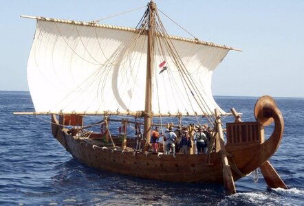
A contemporary reconstructed sailing experiment does give a few additional hints in this port view and the next from more abaft downwind
Reconstruction Aft Downwind Sailing.jpg
one thing that emerges is the large cluster of blocks around to upper mast for the lines that support the yards and may be considered as brail lines on the back of the sail with the brail lines.
The "ornamentation" of the stem and stern extensions has yet to be settled upon as well as the "safety fencing" on both mid-ships gunnels (rope or woven wicker).
I enjoy the investigation while preparing for departure into construction.
Our best wishes to all in SoS who celebrate the Christmas and holidays of this time of year so close to the now past solstice. Rich
 
With some care for alignment, a sharp blade and metal straight edge I cut the plan sheet to move the body plan from left of the body plan and strakes lines, upwards and the shear plan elevation down to align horizontally with the body plan's lines.
View attachment 277457
With this repositioning I will be better able to draw the frames/bulkheads for the hull mold planking with added notches inboard for longitudinal wales matching the gentle curve of the deck and deck beams.
Aside from this I have surfed the net for the most inclusive and agreeable images of the yards and sail rigging. As the only known aspect of these old ships has been taken from inscribed "sketches" in monuments or on stones; or from the painted images on old pottery there is a lot of disagreement in what is seen: both from the artists lack of knowledge, intended distortions or omissions to present what was desired, and/or lack of scale wherein smaller details cannot be shown on the painted/glazed surfaces. A few of the more inclusive images that I have found to blend into my own model I will share a few:
View attachment 277458
the model shows most of the rigging but not in origin or termination details.
View attachment 277459
A contemporary reconstructed sailing experiment does give a few additional hints in this port view and the next from more abaft downwind
View attachment 277460
one thing that emerges is the large cluster of blocks around to upper mast for the lines that support the yards and may be considered as brail lines on the back of the sail with the brail lines.
The "ornamentation" of the stem and stern extensions has yet to be settled upon as well as the "safety fencing" on both mid-ships gunnels (rope or woven wicker).
I enjoy the investigation while preparing for departure into construction.
Our best wishes to all in SoS who celebrate the Christmas and holidays of this time of year so close to the now past solstice. Rich
With the revised plan layout I went back Revised Body Plan Stations Lines.jpgto remark the 1/8 divisions between the five stations lines on the original plan:
Revised Stations 8th divisions and Rabbit Line.jpg
I also added a rabbit line which was not on the plan but inferred by the extended keel in the body plans to the right.
Now I will go back to adjust the frames lines on the body drawing to the right from the half hull plan above and shear plan below. Not drawn at this stage will be carrying horizontally lines over from the shear plan for "notches" in the interior faces of the individual frames/mold pieces.Offsets from body plan and shear elevation.jpg
at this point I don't have any more than the quarter stations lines on the body plan but will add those when I draw the individual frames/mold pieces and try to avoid any more confusion or conflicts that may come out of having too many lines too close together and mixing them up.
The plan file that I received had no scale and the copy shop were limited to paper size and not scale sizing so I am having to proceed with visual and graphic scale of the sheet as it exists which will be sufficient as there is no actual size or scale to any of the ships from the Early Bronze and very few remnants from the Middle Bronze Age. Shipwrecks with hull portions remaining for any recovery are from the Late Bronze age which is still in the future for this build.
Rich
 
With the revised plan layout I went back View attachment 277493to remark the 1/8 divisions between the five stations lines on the original plan:
View attachment 277495
I also added a rabbit line which was not on the plan but inferred by the extended keel in the body plans to the right.
Now I will go back to adjust the frames lines on the body drawing to the right from the half hull plan above and shear plan below. Not drawn at this stage will be carrying horizontally lines over from the shear plan for "notches" in the interior faces of the individual frames/mold pieces.View attachment 277496
at this point I don't have any more than the quarter stations lines on the body plan but will add those when I draw the individual frames/mold pieces and try to avoid any more confusion or conflicts that may come out of having too many lines too close together and mixing them up.
The plan file that I received had no scale and the copy shop were limited to paper size and not scale sizing so I am having to proceed with visual and graphic scale of the sheet as it exists which will be sufficient as there is no actual size or scale to any of the ships from the Early Bronze and very few remnants from the Middle Bronze Age. Shipwrecks with hull portions remaining for any recovery are from the Late Bronze age which is still in the future for this build.
Rich
With the sheet ready to be used in drafting the individual frames I made a set of forty smaller semi-transparent sheets, one for each of the stations and with the enhanced body plan began midships #3:Trade Boat Body Plan Lines and Additions.jpg
Presently this has only the major quarter stations divisions to produce a generalized set of frames:
Trade Boat Firt Frames Drawings.jpg This manual approach is likely slower than CAD where one-half frame could be mirrored very accurately, assuming that the data points for the curving line were accurately and closely identified. In my manual procedure I use a longer ship's curve, a shorter French curve to draw the half frame and then turn the sheet over to draw the second half by tracing it over the original hull line curve.
Trade Boat First Two Frames MIdships.jpg
The time for one frame was about 15 - 20 minutes in the 40 degree garage temperature which slowed the ink flow in the 0.005" pen. This time may reduce a bit but am hesitant about that expectation. When I have the quarter frames for each major section on the shear plan finished I will return to do the eighth frames. That will complete the 40 for the frames' spacing that will serve as the stakes mold and secondarily the frames. For the Frames I am cheating at this point as archaeologists speculate that the hull was the structure with the mortise and tennon or laced construction and frames added in an alternating manner just across the keel if there was one, from each side with some overlap distance across the bottom of the boat. Right not mine will be full across and after the hull has been formed will I consider cutting the shorter part of a frame off to get the alternating lengths layout.
This is going to be slow going so I hope that those falling asleep in their reserved seats don't snore too loudly to disturb the rest of the crew or ancient shipwrights' ghosts lingering to see what it is that I am up to doing. . . I barely know myself and have to learn as I go without their centuries of knowledge and skills. Rich
 
With the sheet ready to be used in drafting the individual frames I made a set of forty smaller semi-transparent sheets, one for each of the stations and with the enhanced body plan began midships #3:View attachment 277685
Presently this has only the major quarter stations divisions to produce a generalized set of frames:
View attachment 277686 This manual approach is likely slower than CAD where one-half frame could be mirrored very accurately, assuming that the data points for the curving line were accurately and closely identified. In my manual procedure I use a longer ship's curve, a shorter French curve to draw the half frame and then turn the sheet over to draw the second half by tracing it over the original hull line curve.
View attachment 277687
The time for one frame was about 15 - 20 minutes in the 40 degree garage temperature which slowed the ink flow in the 0.005" pen. This time may reduce a bit but am hesitant about that expectation. When I have the quarter frames for each major section on the shear plan finished I will return to do the eighth frames. That will complete the 40 for the frames' spacing that will serve as the stakes mold and secondarily the frames. For the Frames I am cheating at this point as archaeologists speculate that the hull was the structure with the mortise and tennon or laced construction and frames added in an alternating manner just across the keel if there was one, from each side with some overlap distance across the bottom of the boat. Right not mine will be full across and after the hull has been formed will I consider cutting the shorter part of a frame off to get the alternating lengths layout.
This is going to be slow going so I hope that those falling asleep in their reserved seats don't snore too loudly to disturb the rest of the crew or ancient shipwrights' ghosts lingering to see what it is that I am up to doing. . . I barely know myself and have to learn as I go without their centuries of knowledge and skills. Rich
Thinking ahead about the best, at reasonable cost of course, what can anyone recommend that I use to cut and shape these frames which are only about 1/8" wide and would be sensitive to grain fracturing when being fared. My assumption would be some type of thin plywood with both finish faces of a species that will take a brownish tone when oiled or lightly stained.
Same question for species for hull and deck planking, again, no paint finishes.
My port has an open dock for all arriving suggestions. Thanks. Rich
 
Not sure which is more ancient, the vessel under design and build, or the tools and methods to do the drawing.

Brings back memories from LONG time ago in shop class.
I resemble that remark. :) Those are the very same drawing tools and methods I learned to do in technical drafting class for doing nautical body form and scantling drawings at the US Merchant Marine Academy. I STILL use those tools.
 
Back
Top