
I'm getting close to rigging the Discovery1789. Time to think about parts. Could anyone give me a rough Idea of how many belaying pins I'll want? 100? 200? 500? I haven't a clue. The Discovery is very roughly the same as the Bounty or the Swan series if that helps.

-

Win a Free Custom Engraved Brass Coin!!!
As a way to introduce our brass coins to the community, we will raffle off a free coin during the month of August. Follow link ABOVE for instructions for entering. -

SUBSCRIBE TO SHIPS IN SCALE TODAY!
The beloved Ships in Scale Magazine is back and charting a new course for 2026!
Discover new skills, new techniques, and new inspirations in every issue.
NOTE THAT OUR NEXT ISSUE WILL BE MARCH/APRIL 2026
You are using an out of date browser. It may not display this or other websites correctly.
You should upgrade or use an alternative browser.
You should upgrade or use an alternative browser.
Kurt Konrath
Kurt Konrath

Does any of the rigging diagrams have numbers for the lines, or some companies give you a "pin" diagram showing which line attaches to what pin in what location.
They are often numbered to give a hint of how many are needed.
I would suggest about 200 to start with so you have some extras as you will drop or brake some.
They are often numbered to give a hint of how many are needed.
I would suggest about 200 to start with so you have some extras as you will drop or brake some.
Thanks Kurt. I don't have any drawings of the running rigging. After I posted I noticed that Mondfeld says there were 150+ ropes so your 200 estimate sounds good. 50 sounds about right for droppage ")
I've been studying drawings of belaying pins and rails all morning and it looks to me like the pins are about a foot apart. I can't find a proper measurement. Is a foot about right? Maybe a little closer?
Take a look here


 www.rmg.co.uk
or also shorter - but this is looking for me too short - it was maybe part of a boat and not for running rigging of a ship


Belaying Pin
Belaying pin carved from a single piece of wood. It has been stained and varnished.Belaying Pin | Royal Museums Greenwich
or also shorter - but this is looking for me too short - it was maybe part of a boat and not for running rigging of a ship
It's the distance between pins that I am looking for.
Would someone take a look at one of their 1:48 models and give me a rough idea of how far apart the belaying pins are? Thanks

Don, my model 1:46 (not 1:58) but thought yours might be similar, measurement-wise....my pins are 5mm apart..Would someone take a look at one of their 1:48 models and give me a rough idea of how far apart the belaying pins are? Thanks


Thank you very much Phil. It would be nice if a couple more could chime in to see an average. 5mm is .2" which is great because my mill moves .1" per turn of the handle.
During searching for the other post
I found several examples and we can see, that the distance between the pins is variable, means it depends on the size and thickness of the ropes
stronger and longer ropes have a bigger distance, which makes sense to have enough space for the rope


smaller and thinner ropes do not need so much space, so the pins can be closer


and somehow in the middle - already a little bit cluttered


Also important I think will be, which types or kind (especially the diameter) of pins you will use for your model? The distance between your pins on the model will be also defined by this
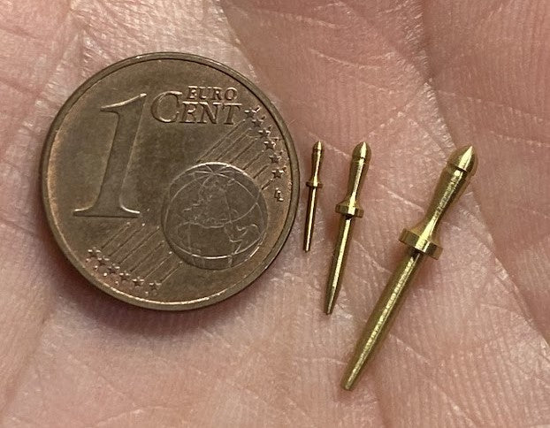
wooden like on @Philski ´s example, or maybe some metal like offered from @Dry-Dock Models & Parts which are much smaller / thinner

 drydockmodelsandparts.com
No room for pin rails.
I'm planning the rigging for the Discovery1789. I'm looking at pin rails at the moment. I'm thinking I need at least 100 belaying pins. The problem with the Discovery is that it has hardly any bulwarks to hang pin rails on. When they raised the quarter deck and the forecastle they made the decks...
shipsofscale.com
I found several examples and we can see, that the distance between the pins is variable, means it depends on the size and thickness of the ropes
stronger and longer ropes have a bigger distance, which makes sense to have enough space for the rope
smaller and thinner ropes do not need so much space, so the pins can be closer
and somehow in the middle - already a little bit cluttered
Also important I think will be, which types or kind (especially the diameter) of pins you will use for your model? The distance between your pins on the model will be also defined by this
wooden like on @Philski ´s example, or maybe some metal like offered from @Dry-Dock Models & Parts which are much smaller / thinner
0.6mm Tiny Brass Belaying Pins 10/bag
Dry - Dock Models & Parts is providing high quality ship model fittings and parts
drydockmodelsandparts.com
Last edited:
Thank you Uwe, I can always count on you for help So this means that before I make/install the pin rails I have to know what is going to be belayed on them. This is getting hard. And I don't know if I'm actually capable of doing all the rigging. Just rigging the guns was difficult and I could hold them in a vice out in the open. From your pictures it does look like I can hang pin rails on the railings so that's a good thing. I'll have to give this some thought.
So this means that before I make/install the pin rails I have to know what is going to be belayed on them. This is getting hard. And I don't know if I'm actually capable of doing all the rigging. Just rigging the guns was difficult and I could hold them in a vice out in the open. From your pictures it does look like I can hang pin rails on the railings so that's a good thing. I'll have to give this some thought.
Did they really have varying spacing between pins or just a standard spacing and if a rope was heavier and /or had a larger coil of rope on it you'd just leave the holes either side of that pin empty to give more space. I seems very inflexible to think that the pitch of the belaying pin spacing would be set by the rail at rime of manufacture.
I'm new at this but I'm getting the impression that the ship builders back then didn't think like us. They seem to have built things for a particular function and that was it. No (or little) standardization. I got my first glimpse into this when I was framing the Discovery. Whereas we would have standard deck sections and/or beams they built each deck and its parts according to it's use and load. Each piece was cut according to what was needed. No 2x4's 2x6's and 2x10's. This makes me think that when they were hanging a pin rail on a bulwark they knew exactly what ropes were going to be belayed on it so they knew the spacing needed. The captains may have changed minor things on the way a ship was rigged but I'll bet he was limited by the size/spacing of the various pin rails.

This stuff works pretty well to get the weathered gray look https://www.micromark.com/Age-It-Easy-Gray
Do you have the lengths of the pin rails? If so then, after determining the number of pins needed on that rail, space them evenly across the pin rail. Another way of looking at the problem is to determine the number of belays needed in a specific area, make the pin rail long enough to carry the number of pins needed spaced an average of 5mm apart at 1/48 scale. Just ideas not knowing what plan set information you may have…
The drawings I have don't show pin rails. The Discovery is one of those ships that "shouldn't be built" due to lack of information.
About a hundred.I'm getting close to rigging the Discovery1789. Time to think about parts. Could anyone give me a rough Idea of how many belaying pins I'll want? 100? 200? 500? I haven't a clue. The Discovery is very roughly the same as the Bounty or the Swan series if that helps.
My current build has 92 installed.....About a hundred.
Thanks. That's better than 150
One of the fun things about the hobby is accumulating a “stash” of pieces, parts, extra wood, etc., to use later especially for kit bashing. After a dozen plus kits I have a healthy go-to stash of extra stuff that I often dig into when building a kit. Sometimes the stash has rescued me when I either broke a part or lost it into the black hole around my workbench…you know…when you drop something on the floor but can never find it again! Anyway…add the extra pins to your stash to use later!