Sorry, it is a stain..What exactly is the Golden Oak - is it a stain?
You are using an out of date browser. It may not display this or other websites correctly.
You should upgrade or use an alternative browser.
You should upgrade or use an alternative browser.
Brigantine Phoenix, by Master Korabel [COMPLETED BUILD]
- Thread starter moreplovac
- Start date
- Watchers 46
Work continues by building deck items, companionways, etc.....
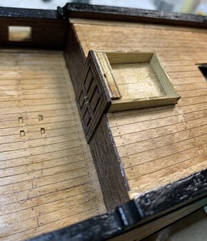
Once sides are installed, the whole structure has to be sanded on an angle so the roof can fit properly.
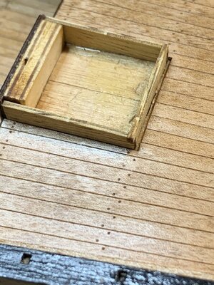
There is a gap between deck and sides i will be covering with a small waterways...
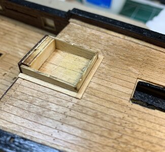
The roof has been installed...
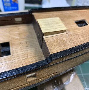
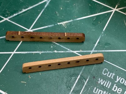
Work on board pin rails is next. Removed from the frames, they have to be cleaned from laser cut burns...
Installed on the ship. They fit very precise with a small adjustments here and there..
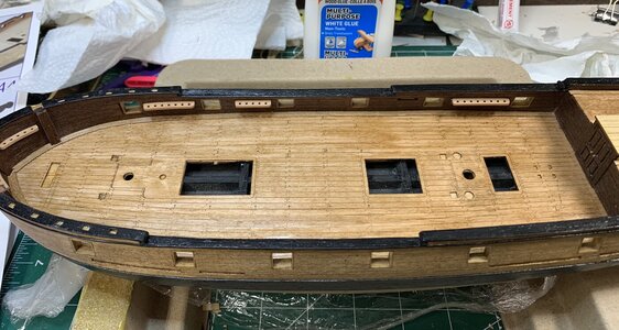
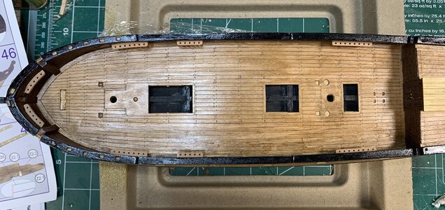
I have not installed all of them, not sure why... but started to work on gratings. The instruction shows how many gratings are required (8x5, 8x10, etc).
Gently installing them, no hard pushing... Some extra gratings are included so no problem if you snap one or two..
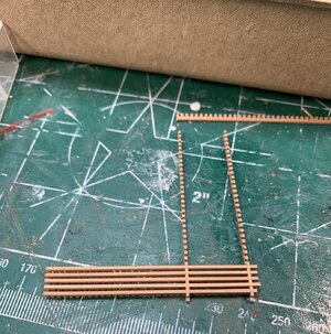
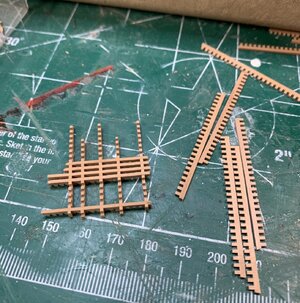
Cut to the size, and glue them from all ends.
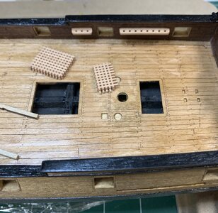
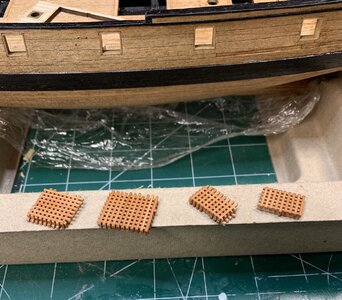
They are ready for final sanding and assembly..
Happy modelling.

Once sides are installed, the whole structure has to be sanded on an angle so the roof can fit properly.

There is a gap between deck and sides i will be covering with a small waterways...

The roof has been installed...

Work on board pin rails is next. Removed from the frames, they have to be cleaned from laser cut burns...

Installed on the ship. They fit very precise with a small adjustments here and there..


I have not installed all of them, not sure why... but started to work on gratings. The instruction shows how many gratings are required (8x5, 8x10, etc).
Gently installing them, no hard pushing... Some extra gratings are included so no problem if you snap one or two..


Cut to the size, and glue them from all ends.


They are ready for final sanding and assembly..
Happy modelling.
Lesson learned.... never blindly trust the instruction sheet.
Made gratings based on instruction dimensions, 8x5 holes as per picture below but actual dimension have to be bigger for at least two more holes, like 10x7..
Not sure was it because of Alvin Lee's guitar riffs or second glass of great french cognac, i finished all needed gratings but did not bother to check the fitting. During assembly phase noticed they are small... Dough..
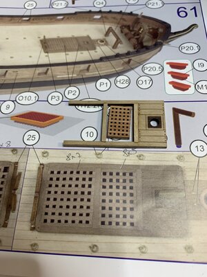
I managed to make three new out of the remaining (and salvaged) gratings but it was not enough for the whole ship..
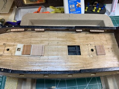
Now i have to either make my own or try to find somewhere gratings that fits the size...
In the meantime continue with other ship parts...
Happy modelling..
Made gratings based on instruction dimensions, 8x5 holes as per picture below but actual dimension have to be bigger for at least two more holes, like 10x7..
Not sure was it because of Alvin Lee's guitar riffs or second glass of great french cognac, i finished all needed gratings but did not bother to check the fitting. During assembly phase noticed they are small... Dough..

I managed to make three new out of the remaining (and salvaged) gratings but it was not enough for the whole ship..

Now i have to either make my own or try to find somewhere gratings that fits the size...
In the meantime continue with other ship parts...
Happy modelling..
The manufacturer usually source different materials over the years, so the instructions have pictures with old style grating...
No problem, it was my bad...The manufacturer usually source different materials over the years, so the instructions have pictures with old style grating...
No worries about gratings, will attack them later.
Continue with skylight assembly. Since they are tiny, i decided to mount them on the piece of tape so it is easier to hold. Then glue them while on the tape..
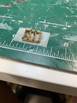
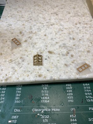
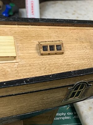
Then to simulate hinges, i cut the small pieces of electrical tape and put them on, following with a layer of varnish to seal the tapes..
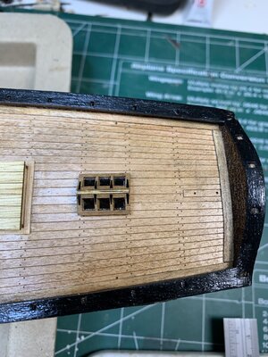
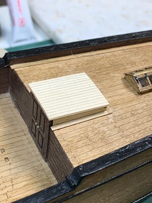
During work on skylight i noticed that companionway roof appears to be a bit out of scale.. Removed it, sanded it, added extra support in the middle and installed a new roof..
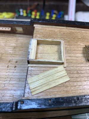
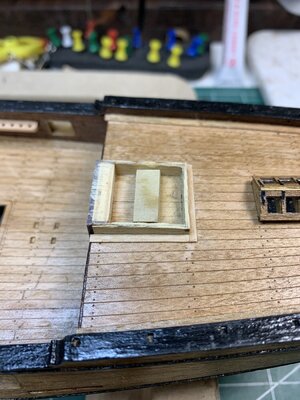
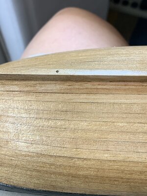
Now it its time to drill a holes for a pedestal in case i decide not to use a cradle... Two pilot holes are drilled.
Horseshoe were attacked next.

First a bath in blackened solution, rinse and dry...
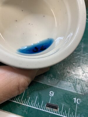
Then glue to the ship..
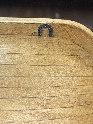
The holes thru horseshoe are drilled to match the diameter of kit provided wire (0.5mm) i will use to simulate nails..
I rounded one end of the nail with a milling bit..
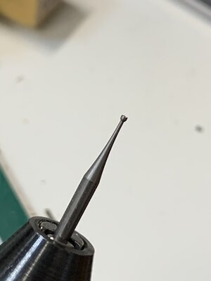
and the nail looks like this:
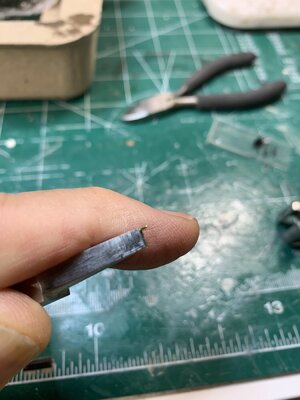
Sorry, not quite focused picture..
And mounted on the ship:
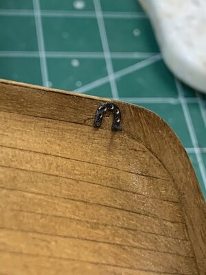
During this process i lost few nails (flew somewhere), but making extras is always a good thing.
Happy modelling.
Continue with skylight assembly. Since they are tiny, i decided to mount them on the piece of tape so it is easier to hold. Then glue them while on the tape..


Then to simulate hinges, i cut the small pieces of electrical tape and put them on, following with a layer of varnish to seal the tapes..

During work on skylight i noticed that companionway roof appears to be a bit out of scale.. Removed it, sanded it, added extra support in the middle and installed a new roof..


Now it its time to drill a holes for a pedestal in case i decide not to use a cradle... Two pilot holes are drilled.

Horseshoe were attacked next.

First a bath in blackened solution, rinse and dry...

Then glue to the ship..

The holes thru horseshoe are drilled to match the diameter of kit provided wire (0.5mm) i will use to simulate nails..
I rounded one end of the nail with a milling bit..

and the nail looks like this:

Sorry, not quite focused picture..
And mounted on the ship:

During this process i lost few nails (flew somewhere), but making extras is always a good thing.
Happy modelling.
The horseshoes were installed..
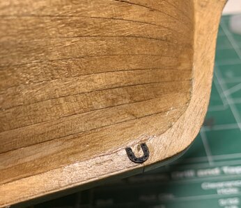
Then the work on rudder started. The rudder is built from two pieces, they have to be cleaned from laser burns, glued and sanded. Then the rudder covers (two pieces of veneer) have to be glued on and rudder shaped in the way that the narrowed part is on the bottom..
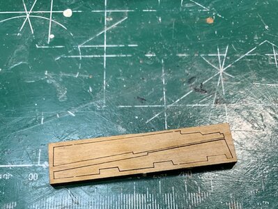
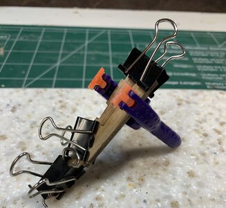
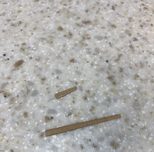
While this is drying, i completed the installation of ship name decoration..
First, cut from the frame, sanded it all...
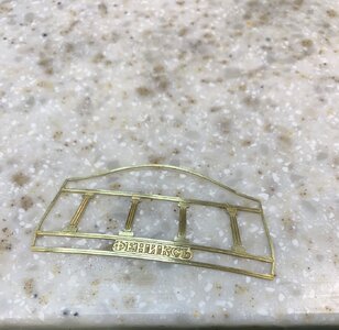
.. short bath in blackening solution and sanded it all again..
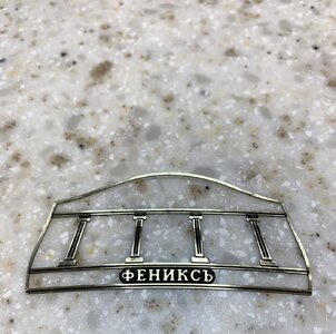
The windows were protected with a piece of transparent tape before the whole hull was painted black.
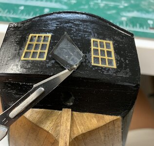
Now, decor will go on by gluing it...
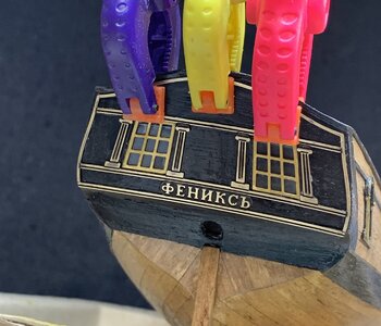
It will stay for now and dry..
Happy modelling.

Then the work on rudder started. The rudder is built from two pieces, they have to be cleaned from laser burns, glued and sanded. Then the rudder covers (two pieces of veneer) have to be glued on and rudder shaped in the way that the narrowed part is on the bottom..


While this is drying, i completed the installation of ship name decoration..
First, cut from the frame, sanded it all...

.. short bath in blackening solution and sanded it all again..

The windows were protected with a piece of transparent tape before the whole hull was painted black.

Now, decor will go on by gluing it...

It will stay for now and dry..
Happy modelling.
Work on rudder and hinges continues..
The rudder has been assembled and sanded to correct shape.
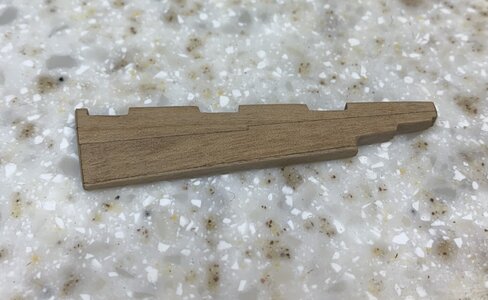
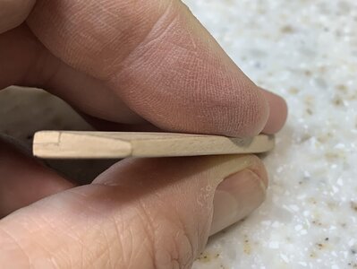
The hinges have been sanded lightly so they can be blackened easier.
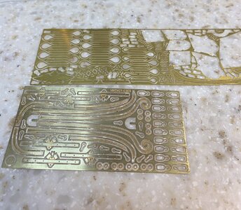
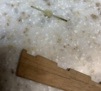
Cut and assembled. The will also be soldered a bit to fill out a gap between parts.
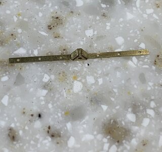
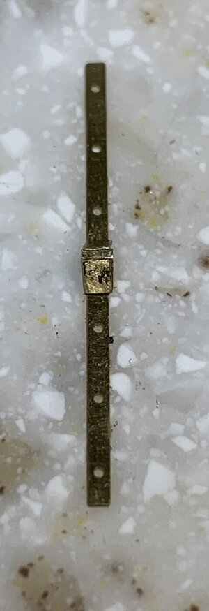
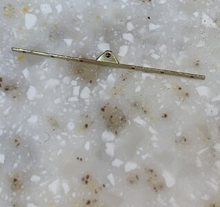
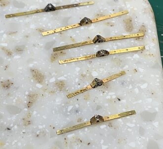
A bit more sanding and soldering a pin as well.. then bath of blackening and ready to be put on rudder.
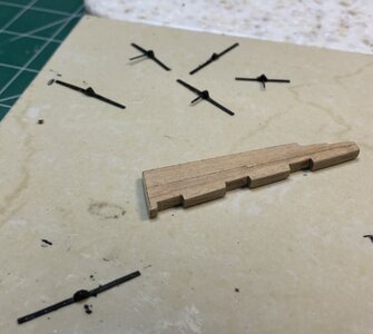
Happy modelling.
The rudder has been assembled and sanded to correct shape.


The hinges have been sanded lightly so they can be blackened easier.


Cut and assembled. The will also be soldered a bit to fill out a gap between parts.


A bit more sanding and soldering a pin as well.. then bath of blackening and ready to be put on rudder.

Happy modelling.
Very well prepare are these hinges - very good detail
The pins are all ready; produced in the same way as before.
Some will be used for hinges on the rudder and some will be used for hinges mounted on the ship itself. And there are few extras because these little buggers fly away on its own..
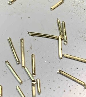
The hinges were glued to the rudder, and pins were cut to the 3mm length and pushed to the rudder. The holes and pins are identical size so pins needs to be pushed into rudder which does not require any glue...
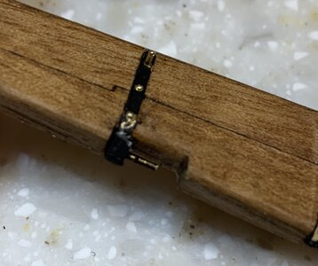
All pins installed. The whole hinges assembly including pins will have to be painted since the blackening was removed during installation process on some rudder areas.
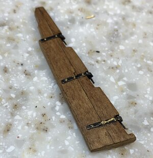
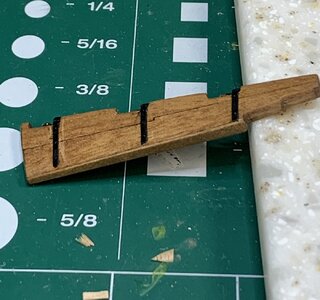
Ready to be mounted on the ship.
Happy modelling...
Some will be used for hinges on the rudder and some will be used for hinges mounted on the ship itself. And there are few extras because these little buggers fly away on its own..

The hinges were glued to the rudder, and pins were cut to the 3mm length and pushed to the rudder. The holes and pins are identical size so pins needs to be pushed into rudder which does not require any glue...

All pins installed. The whole hinges assembly including pins will have to be painted since the blackening was removed during installation process on some rudder areas.


Ready to be mounted on the ship.
Happy modelling...
Have to make few hooks that will be mounted at the bow. Three the same size and one of smaller diameter.
Here is one already made.
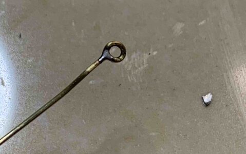
How did i get there? Everyone has its own way of making them so i will just explain quickly how i am making these.
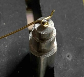
First twisting it around the correct diameter.
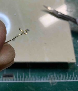
End product..
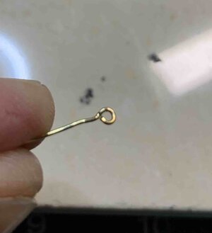
Cut the excess of wire so the hook is a hook..
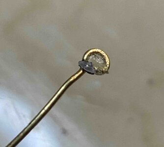
Preparing for a soldering..
Soldered..
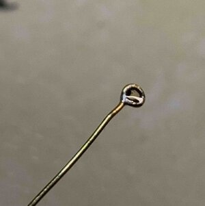
Cleaning the hook..
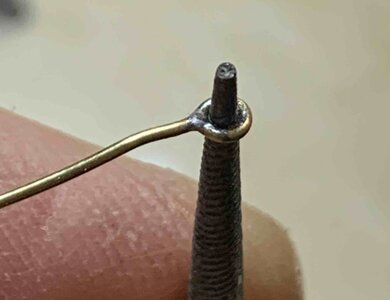
Few done and some extras...
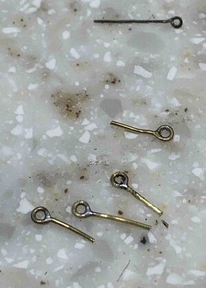
Happy modelling...
Here is one already made.

How did i get there? Everyone has its own way of making them so i will just explain quickly how i am making these.
First twisting it around the correct diameter.

End product..

Cut the excess of wire so the hook is a hook..

Preparing for a soldering..

Soldered..

Cleaning the hook..

Few done and some extras...

Happy modelling...
The rudder has been installed...
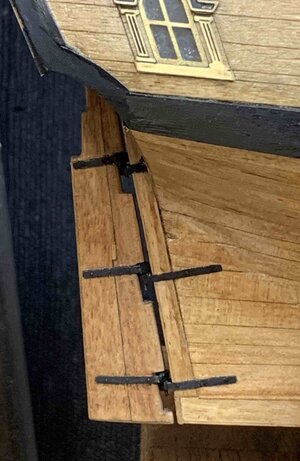
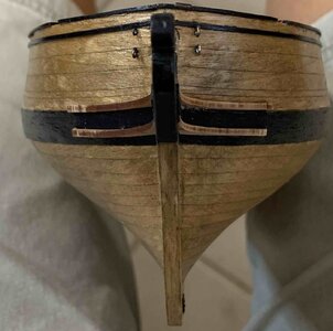
Then crossbar installation took place by first installing a part on the stem aligning it with a hole. The second part is double veneer and the first one i have installed as one piece (both veneer layers at once).
In the middle of gluing the top part dislocated and fall off.. The second part was done differently: first both layers were separated and installed individually. Way easier..
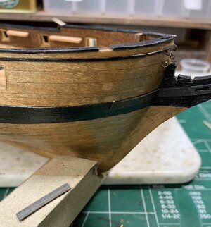
The knee has to be bevelled a bit and soaked in water so it can be easier bend while assembled..
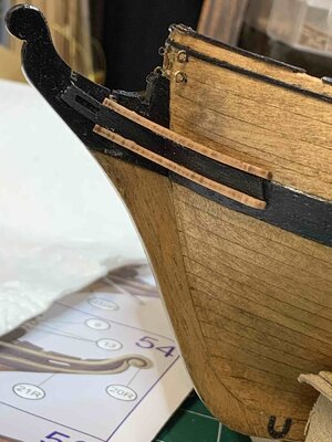
Next, knees have to be filled a bit to be parallel but that is next step..
Happy modelling...

Then crossbar installation took place by first installing a part on the stem aligning it with a hole. The second part is double veneer and the first one i have installed as one piece (both veneer layers at once).
In the middle of gluing the top part dislocated and fall off.. The second part was done differently: first both layers were separated and installed individually. Way easier..

The knee has to be bevelled a bit and soaked in water so it can be easier bend while assembled..


Next, knees have to be filled a bit to be parallel but that is next step..
Happy modelling...
Looks great! I like your way of making eyebolts. I'm always lazy and use ones from kits.
I noticed that there is no hole in your stem. There has to be one for bowsprit lashing. You had it in your previous pictures.
I noticed that there is no hole in your stem. There has to be one for bowsprit lashing. You had it in your previous pictures.
It is still there, just hidden thru picture view..Looks great! I like your way of making eyebolts. I'm always lazy and use ones from kits.
I noticed that there is no hole in your stem. There has to be one for bowsprit lashing. You had it in your previous pictures.
Cheers
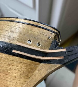
It is time to work on hawse holes. The notches in anchor lines are used as a guides to drill holes in the hull..
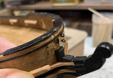
It's always a scary part when you need to drill a hole thru the hull... hard to fix any mistake.
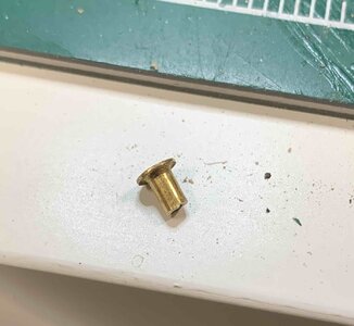
Hosepipes are shortened to 6mm length so they dont stick out too long from the inner side..
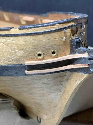
The glue was applied in the opened hole and pipes are mounted in.
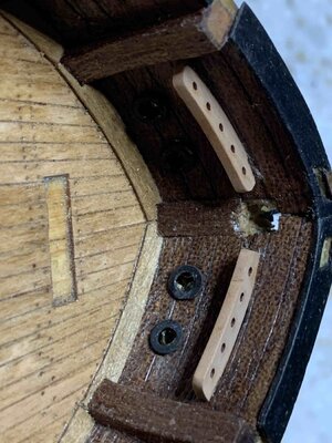
To cover the opening on the back, i made few metal covers. First i made rings out of the brass wire, soldered it and flattened them. Then short bath in blackening solution and glue them to the ship.
Maybe next time i play with milling metal covers...
Happy modelling..

It's always a scary part when you need to drill a hole thru the hull... hard to fix any mistake.

Hosepipes are shortened to 6mm length so they dont stick out too long from the inner side..

The glue was applied in the opened hole and pipes are mounted in.

To cover the opening on the back, i made few metal covers. First i made rings out of the brass wire, soldered it and flattened them. Then short bath in blackening solution and glue them to the ship.

Maybe next time i play with milling metal covers...
Happy modelling..
I like your metal covers on the inside! Great idea. I should start doing that too. How do you determine the radius of the loop?
I measure the outer dimension of the pipe and used it as inner radius for a loop (kind of in the picture). This was used to choose a size of the drilling bit i used to make few loops. Loops were soldered and flattened with small hammer and anvil.I like your metal covers on the inside! Great idea. I should start doing that too. How do you determine the radius of the loop?

Hello, Moreplovac. When you flatten the hoops, the inner diameter will make it smaller. Is this correct?I measure the outer dimension of the pipe and used it as inner radius for a loop (kind of in the picture). This was used to choose a size of the drilling bit i used to make few loops. Loops were soldered and flattened with small hammer and anvil.
If you are careful and try to hit the outer side of the wire (ring) you might lower the result of diameter shrinkage..Hello, Moreplovac. When you flatten the hoops, the inner diameter will make it smaller. Is this correct?
Since this ring was glued to the inner bulwark and pipes do not stick out all the way (i cut them), you actually not seeing any discrepancy in diameter size. The best way would be to actually mill the inner cap (lets call it that way) but i don't have an option to mill it so i have to do it all fashioned way. I blackened it to hide different colours of copper and soldering material.
I might make a tiny cap out of a wood and paint it in black just for fun or leave it in natural wood colour. The other option would be to make the cap out of plastic tube or something and put a layer of flat black on it...


