Brigantine Phoenix

Joined
Aug 26, 2020
Messages
324
Points
238

Location
UK Dorset

This will probably be more of a twig then a log. Moreplovac has written a wonderfully detailed build log for this model accompanied by magnificent photos which I am quite incapable of matching. I will confine this log to aspects which reflect my personal experience of building Phoenix.
I chose this model for a number of reasons. I have just completed the Corel Vasa after almost a year of work. This involved a lot of very repetitive work: gun ports, gunport lids, ratlines etc. so I fancied something a little simpler. All previous builds have been 3 or 4 masted so a brigantine is appealing. Comments on this site have spoken in favour of this kit manufacturer and I am intrigued by the inclusion of specially shaped planking.
Also, I am running out of space for displaying any more large models but there is space of limited height on top of a bookcase that I can commandeer without causing a mutiny. The Phoenix will fit there and can engage in war games with Golden Hind. On previous builds I have wimped out of including sails. I shall venture into this new territory on this build. Again, a brigantine seems to be a bit less ambitious than, say, Cutty Sark (with studding sails of course).
I was very impressed during the initial stages of building this kit. The pieces such as keel, bulkheads and decks are very accurately cut; they fit together beautifully and positively. The plans and diagrams are clear and detailed. The translated instructions are occasionally (and understandably) a bit confusing: references to the "conductor" baffled me for a while until I realised the alternative translation "guide" would have been more familiar. English has too many synonyms with nuances!
The problems began when I got beyond this initial stage. The quality of some of the materials in the kit is very poor. More on this later.
 
Many Thanks for starting this new log - I will follow your work with interest
 
First Stage Planking.
The instructions suggest soaking the planking to facilitate bending so I put a preliminary batch of five starboard side planks into a jar of water.
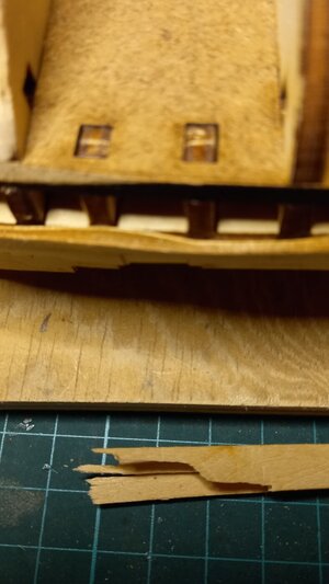
A BAD MOVE. The plywood strips completely delaminated and left me with a pile of shards. An example appears at the bottom of the photo below.
plank3.jpg
Damage limitation.
I have available: 5 mm wide lime strips left over from previous builds and some good quality 2 mm and 0.9 mm plywood;
Option 1 would be to replace the area covered by the destroyed kit components with lime strips applied the old fashioned way. This would negate one of the attractions of the Korabel kit with its pre-shaped planks. Also, it would be difficult to interface the patch with the remaining, undamaged planking.
Option 2 would be to use the undamaged port side, pre-shaped planks as a template to cut replacements from the 2 mm ply. The kit planks are actually about 1.7mm but the interface could prabably be sanded away. Cutting the 2 mm strip involved using my ancient treadle fretsaw machine. I got a fairly good match but still had to do a bit of trimming to get an accurate reproduction of the original. Also, the fretsaw is out in the garage and its rather cold out there.
Option 3 was to cut two pieces of 0.9 mm ply for each original plank. The thin ply is readily cut with a sharp blade (indoors!) and although it sounds like doubling the work it was fairly easy to cut the necessary pieces using the port side originals as a guide followed by minimal trimming. The 0.9 mm plywood is extremely flexible so does not need soaking - even though it would probably survive. This option was the one adopted.
I reproduced and fitted the first five starboard side planks then continued with the hitherto undamaged planks - dry fitted!
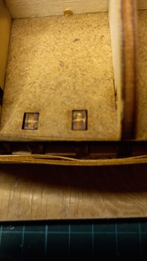
The problems did not stop here. Even on a gentle curve, and with no soaking, the plywood in the kit was prone to separating into layers. Th upper part of the above photo shows the inner layer of the plywood (presumably under compression) bowing inwards as it is bent round the bulkheads.
The photos below show some further disasters.
Plank6.jpg plank2.jpg

The neat and ingenious design of this Master Korabel kit is completely ruined by the use of rubbish materials. (a ha'peth of tar comes to mind) The idea of the shaped planks should have made the first stage planking quick and easy. Instead it extended the effort required beyond that of the conventional straight strip method.
I wonder if the guy who made this batch of plywood got confused while making his lunchtime butties and spread jam on the veneers by mistake. I hope his teeth are still stuck together.
 
Or contact Master Korabel direct…

It is always harder to repair than to build new. Whatever method you use have patience…pull off all the damage then try to duplicate and fit new parts. Let us know how you resolve the problem.
 
As I know, Master Korabel replaces all the defective parts cost-free. You need to contact the shop where you bought the kit.
Thanks for the info. I didn't know that I might have been able to get a replacement and have now struggled to completion of the first layer planking.
I'm not sure that the replacement option would be available in the UK. Out of interest, I contacted Cornwall Model Boats to ask about this and they said they would look into it.
 
Sail Making
This is my first attempt at making sails for a model so I am very much at the bottom of a learning curve.
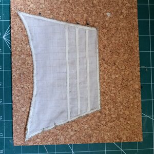
I had hoped to simulate the joins between bolts of sailcloth by drawing out threads at intervals across the width of the sail. Attempts to do this with the cloth provided in the kit were not very successful. I could catch a loop of a chosen thread with the tip of a needle but if I tried to pull it out it just broke. Trying to pull the broken ends with a pair of tweezers just produced micro oakum. This is very frustrating: if I catch my trousers on a splinter or nail it pulls a thread the length of my leg. But 8 cm of sailcloth - no way! I do have an old pair of trousers destined for the big wardrobe in the sky but I don't think charcoal grey cavalry twill would make very convincing sails.
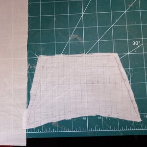
To experiment with the technique I cut a sail shaped piece from an old, often boiled handkerchief. With care I could draw out threads as required - sometimes the whole height of the sail or, failing that, in two parts. Given that the said handkerchief material is about the same weight as the supplied sailcloth I decided to use this for all the sails rather than source cloth with unknown properties from other kit manufacturers.
The Phoenix plans seem to suggest cutting the sails with a 3 mm margin round the final outline and folding this inwards to form bands round the perimeter. As few of the cuts would be parallel to the warp or weft I was 'afrayed' this might become messy. Also, the reef bands are intended to be cut as strips of cloth. To simplify both requirements I bought a 10m length of 3 mm wide woven cotton tape.
The first photo below shows a rough curt of a sail with trhreads drawn out. A piece of the sailcloth from the kit is include in the picture for comparison. The bogey mop material is slightly more sheer.
The second photo shows the sail with the bands attached and the edges trimmed..
Sail1.jpg sail2.jpg

Bolt ropes
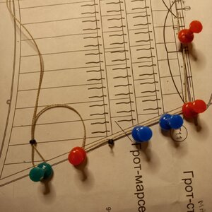
The first photo below shows the preparation of a section of bolt rope. The cringles are created by pulling loops through parrel beads left over from a previous build. These are located by tightening the loop round a pin. The second photo shows the completed bolt rope sewn round the edges of the sail. The use of the woven cotton tape for the bands meant that the stitches could be made very close to the edge without pulling out any thread. I believe stitching is supposed to pass through the bolt rope rather than round it but an attempt to do this proved difficult - especially since the bolt rope contained adhesive from its preliminary fixing round the sail. Some of the beads on the cringles have been left in place for illustration.

Cringles.jpg sail3.jpg

Reef Bands.
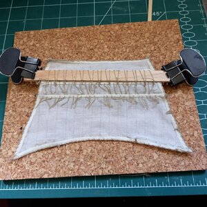
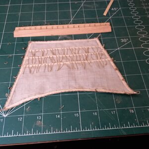
I'm afraid I was too lazy to add the reef points individually: I used two strips of ply with pins attached to add them as a continuous winding. A spot of PVA on each side if the reef band where the thread passes through seems to hold them in place - they are not under any load. The loops on the formers are subsequently cut to form the individual points.
The first photo below shows the initial winding; the second shows the completed sail. The reef point formers are included in this photo.
sail5.jpg sail6.jpg
 
second stage planking.
After the problems encountered in the first stage planking I was relieved to find the second stage relatively easy.
The individually shaped planks of the Master Korabel kit fit together very neatly. Essentially they taper and curve down towards the bow and widen a little towards the stern. The net result is that the tendency for planking to turn up towards the bow is countered by the downward curve of the planks. The joints between the planks remain more-or-less parallel to the keel. Whether this is historically accurate or not I don't know but it is aesthetically pleasing.
I wonder what would happen if, on a future build, I replaced the usual kit-supplied planking strips with shaped strips cut from a sheet of veneer on the Korabel principle. Would the downward curvature be critical or would it just be of general help? Scope here for interesting experimentation.
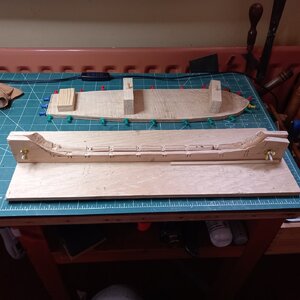
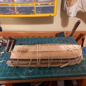
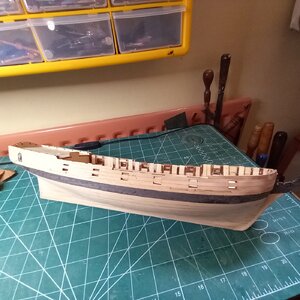
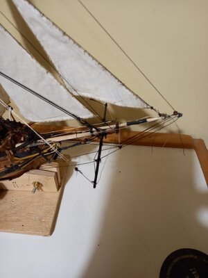
The first photo below show the supports I used for the hull upright or inverted. The improvised keel clamp offers some support for the stem and stern posts to ease the load on the keel. When fitting the upper planking I used 4mm wide strips of 1mm plywood screwed at intervals along the keel clamp. These could be wrapped round the recently added planks and clipped to the bulwarks. For the lower planks the other support was used for the inverted hull. The blocks put the support onto the deck rather than the bulwarks. The pegs plug into mast holes. Added planks are held in place with a tangle of rubber bands placed as required. Scraps of wood could be tucked under the bands if necessary to apply local pressure. (picture 2)
The third photo shows the completed second stage planking.
Aside: A common scale for ship modes seems to be 1:72. Is it significant that this corresponds to One inch to the fathom?

Bases.jpg Plank9.jpg

Plank10.jpg
 
Eye bolts
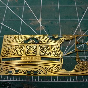
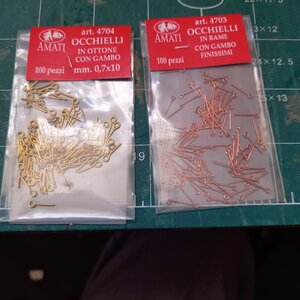
The eye bolts supplied with the Master Korabel kit are pretty naff: they are part of an etched brass sheet. Using them would require tedious cutting out and the extractions would be flat and unrealistic. Rather than mess about bending bits of wire I bought packets of 2mm and 3mm Amati eye bolts costing all of £1.50 each for 100.
The breech ropes on the cannons pass through a ring attached to an eye bolt on either side of the carriage. To make each of these I opened up the eye of a 2mm eyebolt, hooked it through the end link of a length of brass chain (left over from an OcCre model), closed the eye then cut the penultimate ling. After fitting to the carriages I painted them black. In principle a similar process should be used for the ends of the breech rope at the bulkhead but I decided simply to use 3mm eye bolts and dispense with the ring. The distance between the carriage pins and bulkheads is so short that a ring could only just be accommodated and the simpler option is masked by the loop of the breech rope. Not authentic perhaps but easier.
etching.jpg eyebolts.jpg
 
Phoenix Deck furniture and fittings.
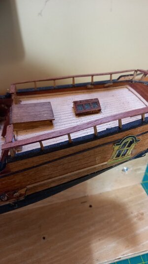
In the early stages of the build I was impressed by the accuracy of the laser cut structural parts: keel, bulkheads, deck all fitted together very well. However, this production technique seems to have been carried to ridiculous extremes. Virtually every part is laser cut from wooden sheets of various thicknesses. For example, the posts supporting the stern rail are all individually cut from a sheet. Each had to be removed; the burnt edges needed to be cleaned for cosmetic and adhesion purposes. It would have been far easier to have cut lengths from an appropriate strip or dowel - as would be the case in most other kits I have tried. The bases of the cannon carriages are laser cut and include the wheel axles (square!). Each had to be rounded to fit the holes in the trucks. Forty eight fiddly bits of filing. A length of axle rod (metal or wood) to be cut into short lengths would have been less tedious. Rubbing strakes, ladder rungs, hatch coamings were all laser cut and in need of cleaning before installation. The only wooden strip provided was that around the deck where it met the gunwales.
Then there is the plethora of etched metal accessories: eyebolts (remarked on earlier), hooks, block strops, deadeye hounds. Aaagh!
SternRails.jpg
 
BowsPLits
I hate bowsprits! They are long, vulnerable and tend to hang off the end of my work table. I usually defer fitting them as long as possible but the Phoenix has so many things connected to its bowsprit that I needed to fit it sooner than I would have liked. I was very careful when it became necessary to wear ship: I always turned the bow towards me to keep an eye on the bowsprit. But inevitably I managed to break it - twice. The first time I reached out to adjust the anglepoise without looking and dragged it across the bowsprit. I effected a rather crude repair with a collar made made from a short length of dowel drilled out to receive the broken ends.
The second time I caught it in my Jersey while reaching past it. This time I found a short length of copper tube in a packet of offcut tubes and rods I found on e-bay. The bore was just right to receive the broken ends. Painted black, it almost looks like an intended fitting.
Bowsplit.jpg sprirepair.jpg
 
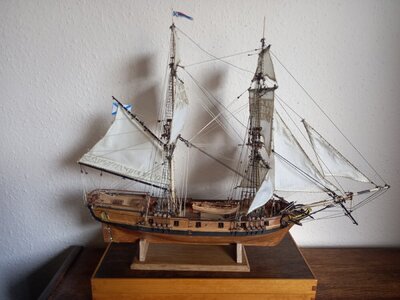
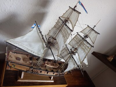
Phoenix completed
The rigging stage was fairly straightforward though It proved impossible to get the supplied thread through the beautifully shaped blocks in their basic state. In creating the impression of pulleys in a sheave the holes for the thread do not go directly through the blocks. I couldn't even get a needle threader through. I resorted to drilling a straight through, 0.5mm hole which solved the problem without affecting the outward appearance of the rigged blocks.
Frankly, I am glad to see the end of this kit! It had some good points but these were outweighed by the quality of some of the materials and the obsessive use of laser cutting for miniscule parts. As for photo etched eyebolts....
Back to OcCre I think.
phoenixd4.jpg phoenixd5.jpg
 
Back
Top