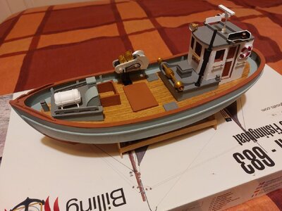
Mary Ann by Billing Boats 472 - Build log

The motor mount
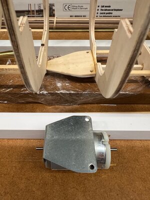
The mount for the motor is very simple. I used a piece of the 5mm ply left over from the laser-cut sheets, cut to the size of the mounting plate and long enough to go across the gap between frame 6 & 7, with appropriate bevels to the ends and underneath to match both the angle to the frame and the alignment for the shaft. There is also a small wedge under the platform, on top of the keel, and later I added a couple of wedges underneath at right angles to the keel. It will all be epoxy glued together.
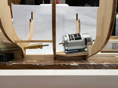
1709175362239.jpeg

Looking good, until I realised (before gluing) that the outer hull planking is going to clash with the lower corner of the timber platform and probably any bolts I put in the aft set of holes of the metal mount (red highlight below). My solution was to hacksaw off the rear corners of the motor mount (orange dotted line below) and shape the timber platform to match.
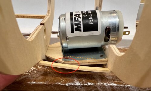
1709175437069.jpeg

Like this…

1709175465587.jpeg

The motor doesn’t produce a lot of torque, so I think it would be fine with just two bolts…but, to be sure, to be sure, I’ll add (using epoxy) a small angle bracket to the rear nose of the mount so that it can be screwed centrally into the keel.
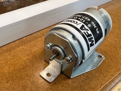
1709175610894.jpeg

Next time, a bit of bracing.
 
Thanks Sevish. I was having a look at your Santisima...that's just a magnificent build, I can only imagine the patience required for the rigging on a ship like that.
Thank you pete.
Indeed , lots of rigging and lots of patience especially when the rigging plans are raises some question marks.
 
Extra Bracing
I don’t know if this is really required, but the kit was designed as a static model, so things like the stern post and keel are fairly light dimensionally. Add to that fact that I have cut and glued the stern post in a couple of places for the shaft and rudder, I feel that a little extra bracing (while it's easy to do) would be prudent.

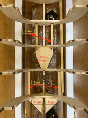
Nothing fancy, I added a couple of largish right angles of 5mm ply around the stern post and attached that to frame 8, then I’ve added further 4x5mm braces from the edges of those through to the next frame (same for the motor mount)…I’m sure there’s a ship building term for those, but I don’t know what you’d call them (shown as ‘bars’ in the photo).

1709357535323.jpeg

That’s all, it doesn’t add much weight, and probably isn’t really needed once the planking and deck are in place…but I felt better having added them ;)
 
Battery Box
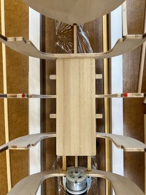
It’s really just a platform, with a couple of cross bars that I can loop an elastic band around. There is a fairly flat area ahead of the motor that makes this an easy fit. It will hold a battery up to 140mm long, which will easily handle the LiPo batteries I was looking at. They’re also fairly light at around 300g, so it’s unlikely to cause ballasting issues when I get to that stage.

1709357778557.jpeg

Here is something that I’m still thinking about… the battery area is forward of the opening in the deck where the wheelhouse will sit (that’s over the motor and coupling). When I can test fit the deck, I may find that there’s sufficient room to slip a LiPo pack in and forward, although I doubt that I’d be able to secure it with a rubber band. I noticed that Bob Vaughan cut an additional large access opening between the deck winch and forward mast, above the area where the battery box is…I may do the same, or a smaller variation just to allow me to slip on the elastic bands. There are some on-deck features (boxes for fishing gear) aft of the mast that might work as a mask over the area, without it looking obvious.

The platform used above is 3mm Paulownia sheet, and the bars glued underneath are the same.

An aside for my fellow Aussies…
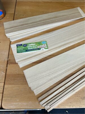
I found Bunnings selling Paulownia timber in hobby packs. It is inexpensive (the pack was around $20 for 20 varied pieces - sheet and square section - see photo below), plantation grown in Aus, light like balsa, but with the 'strength of western red cedar' (their claim)…it’s like a hard balsa. It is very clear grained and cuts nicely. They’re only 450mm long, but I thought I’d mention it in case it is useful info for someone
.


1709358057715.jpeg

Next time I'll have a look at mounting the rudder servo.
 
Rudder Servo Mount
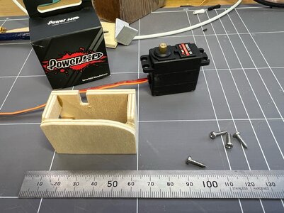
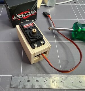
Another custom item for the build is the mount for the servo to drive the rudder. I bought a micro-servo as I don’t have a lot of room under the deck, but it’s reasonably powerful for its size (PowerHD HD-1250MG).

I’ve chosen to place the servo across the keel, immediately aft of frame 8, so that I can get access from above to the screws at each side, in case I need to remove the servo at some point. Having it mounted across the keel also means that I do not have to cut a large bite from the stern post (the post is quite light as it is). The frame or box has been made to fit the case of the servo - it had to be made slightly longer than the servo so that the servo can be angled during fitting to allow the wiring through, before it is screwed down. The mount is a made of 5mm ply and will be epoxy glued to the angle bracing around the stern post and over the floor of frame 8.

Here (below) is a photo of it upside down showing the shaping needed to fit the area.

1709706438362.jpeg

And the fitted servo…

1709706466463.jpeg

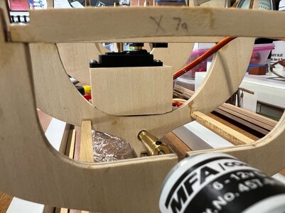
And here it is in position, ready to be glued in. The deck beams across the top of frames 7 & 8 will be cut to provide the opening under the wheelhouse, this will also allow for the throw of the servo horn without fouling anything.
1709706505278.jpeg

The model plans have a small quarterdeck at the stern, conveniently over the rudder tube, so I plan to make that removeable for access to the control horn at that end.

At this point I realised that I can’t test anything without a radio and receiver - and these haven’t been purchased yet as this is also my first RC project - so I need a way to test and check the swing of the rudder.

One of my other hobbies involves building electronics and often circuits run using a micro-controller…and sure enough there are examples of servos being driven by a very simple circuit using an Arduino as the controller (there’s a library that does all the heavy lifting). I had an old UNO sitting in stock doing nothing, so this circuit now allows me to test the servo. It’s nice when interests in different areas of life come together to help out.

1709706551939.jpeg

The small potentiometer (lower right) can be rotated to swing the servo through its full 180 deg travel. This is for testing only, it will be replaced by the radio solution before too long.
 
Battery Box
It’s really just a platform, with a couple of cross bars that I can loop an elastic band around. There is a fairly flat area ahead of the motor that makes this an easy fit. It will hold a battery up to 140mm long, which will easily handle the LiPo batteries I was looking at. They’re also fairly light at around 300g, so it’s unlikely to cause ballasting issues when I get to that stage.

View attachment 431858

Here is something that I’m still thinking about… the battery area is forward of the opening in the deck where the wheelhouse will sit (that’s over the motor and coupling). When I can test fit the deck, I may find that there’s sufficient room to slip a LiPo pack in and forward, although I doubt that I’d be able to secure it with a rubber band. I noticed that Bob Vaughan cut an additional large access opening between the deck winch and forward mast, above the area where the battery box is…I may do the same, or a smaller variation just to allow me to slip on the elastic bands. There are some on-deck features (boxes for fishing gear) aft of the mast that might work as a mask over the area, without it looking obvious.

The platform used above is 3mm Paulownia sheet, and the bars glued underneath are the same.

An aside for my fellow Aussies…
I found Bunnings selling Paulownia timber in hobby packs. It is inexpensive (the pack was around $20 for 20 varied pieces - sheet and square section - see photo below), plantation grown in Aus, light like balsa, but with the 'strength of western red cedar' (their claim)…it’s like a hard balsa. It is very clear grained and cuts nicely. They’re only 450mm long, but I thought I’d mention it in case it is useful info for someone
.


View attachment 431859

Next time I'll have a look at mounting the rudder servo.
Hopefully and with all fingers crossed, Bunnings will introduce this into the NZ market.
 
Finalising the rudder linkage

Hi, I’ve been away doing other things for the last week or so, but I’m back to the slip to finish off the rudder linkage to the servo. I didn’t have anything ready made to handle the rudder end of the linkage, so my thinking is…
  • Add a collar to the top of the tube that the rudder post runs through. This will act as an upper bearing face for the shaft. It is the same as the simple brass collar that I bought for the shaft itself (see next point). I’ve drilled it out to fit the OD of the tubing that the shaft runs through. It will be epoxy glued to the tube, rather than attached using its grub screw, as I don’t want to crush the tube out-of-round.
  • Another matching collar will be attached to the shaft itself, using the supplied grub screw.
  • A control horn cut from brass sheet will be attached to the collar on the shaft.
  • A linkage from the servo horn to the rudder horn will be made up using brass wire, and the ends will be bent to keep the linkage in each horn.
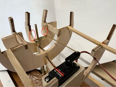
And below is a photo of it installed and hooked up to the servo. The red circles show where I had to remove some wood from the bulkheads to ensure smooth passage of the arm. The rudder post was shortened to just 3mm exposed, after taking the photo.

1710918698830.jpeg
 
Finalising the lower end of the rudder post.

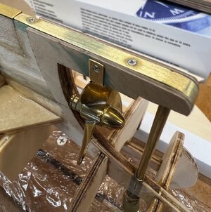
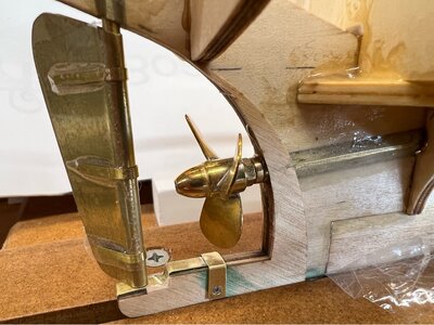
I had to put off finishing off this part until the fine stainless screws (M1x10 countersunk, 304) arrived…the first batch were lost in the post and had to be re-ordered. These are to hold the brass strip to be lower keel extension and allow it to be removed if I want to drop the rudder out. During the fitting I realised that I wouldn’t be able to get a screwdriver in at a suitable angle to drive a screw from the top side, so I made up a small saddle and soft-soldered it to the fitting and put shortened screws in from the side (at different heights so they wouldn’t clash).

1710918781385.jpeg

The cheeks on the extension hadn’t been glued when the photo was taken. Below is one from the side with the rudder temporarily in position. The green stain on the timber around the screw holes is Tanalised Ecoseal, it helps prevent rotting, but I may drill out the holes to 2mm, then fill them with epoxy and re-drill for the screws before I seal everything.
1710918813739.jpeg

Next time, some wiring...
 
Motor and ESC Wiring

The motor is supplied bare, with no wiring. I purchased some red/black 15A rated, pre-tinned multicore wiring to connect the loads with a higher current (nothing is really ‘high’ current, relatively speaking in this design, the motor has a 5 amp stall current). After some research, I’ve decided to standardise on XT type connectors. I like that they are directional when mating, don’t have annoying clips but do have a nice press fit when brought together, they provide a landing for glue coated heat-shrink to secure to at the fitting end, and they come in a number of standard sizes for different current carrying purposes. I’ll be using XT60s for the main loads and XT30s for the lighting etc.

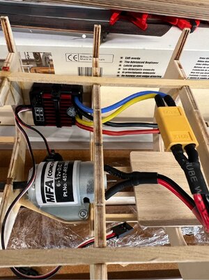
The wiring runs are all relatively short, and in this build they are standard and fairly simple. The ESC will be mounted on a ply backing board glued between the frames under the deck opening, secured with a zip-tie. Given that it is running a very light load, relative to its design specs, I don’t expect any significant cooling issues.

Although I don’t have my radio gear yet, I plan to mount the receiver under the floor of the wheelhouse as shown in Bob Vaughan’s photos (linked earlier).

1711432586897.jpeg
 
The deck

The kit provides a thin 3-ply deck…it is the structural member, but it has a veneer of 0.5mm thick planks to be laid over top. The deck is laser-cut to handle the horns of the bulkheads and is split into two halves lengthwise to ease installation. The deck has both sheer and a slight camber to conform to. Before installation I found that I needed to do some careful sanding of the deck beams to get a consistent curvature of the camber across the deck.

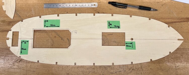
I have pre-cut the access holes to the hull that the wheelhouse, quarterdeck and forward fish boxes will sit over, because it is much easier to do flat and off the frame of the boat. When fitting the deck, I found that the tops of some of the frames didn’t align perfectly with the pre-cut deck slots (I should have dry fitted the deck while the longitudinal deck beams were being glued to the frames to set them in the correct spots), but it’s only by a millimetre here and there, and there is sufficient give in the bulkhead material to allow me to pull those into alignment without distorting the frame. Just getting the deck in under the curve of the tops of the frames and then forming to the sheer requires some tricky bending and careful force, but it looks good when in place.

I’ve added the dimensions I’ve used to some tape in case anyone is reading this later (there is no plan info for these).

1711433162379.jpeg

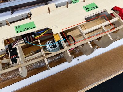
One more thing to check…that hole behind the mast is to give some access to the battery, mainly to allow fitting of bands to hold it in place. Now, I didn’t want to glue everything in and then find that I couldn’t get the battery in. I haven’t bought the battery yet, as I want to do some testing under load before I commit to 2S or 3S for the LiPo, so I made up a dummy of the 3S battery using scrap MDF (red outline below) to see if it fits. It does, but not through the forward hole, it has to be slid in from the larger opening over the motor (see blue arrow), which works fine.

1711433202636.jpeg

Another change that I made (and can be seen in the photo above), is to move the ESC back by one set of frames. I had made a simple mount between frames 6 and 7, but that leaves it covered a little by the deck opening, so I added another mount between frame 7 and 8 and also moved it a little lower in the hull. I think it will work better there. The ESC switch and the radio receiver will be mounted above it in a removeable deck under the wheelhouse. The wheelhouse in this design is raised above deck level so there will be plenty of room to fit everything.

I wasn’t sure about whether to soak the ply decking prior to installing (thinking it might have made bending easier), so I asked on the forum https://shipsofscale.com/sosforums/threads/installing-a-ply-false-deck-soak-or-not.13882/ and the advice was to glue it dry to ensure that I don’t de-laminate the ply by hot-soaking it.

After test fitting, I decided to use slow CA on the inner sections of the deck beams, get the sheer right, and let that dry, then use thin CA and capillary gluing of the outer beams while I pulled the camber into place. It was pinned as I went and I think it has gone pretty well…stressful at the time, but in hindsight it’s all smooth sailing!

The final step was to give the underside and bulkhead frames a spray of sealer (clear acrylic) before I lose access to the underside/inside when the planking starts.
 
So, the frame is now complete, and is now ready to start the planking…a new skill for me to develop. I’m doing some reading for the moment and I will be taking my time with this part of the build. I’m sure I’ll be asking questions at some point, but until then I’m going to fill you in on some of the other build that I’ve been doing 'above deck' when I’ve come across delays up to this point…

Deck Fixtures
Most of this was built a month or so back while I was waiting for the delivery of parts needed for the drivetrain described above.

The winch
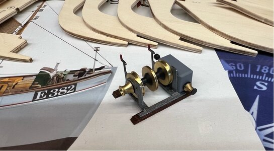
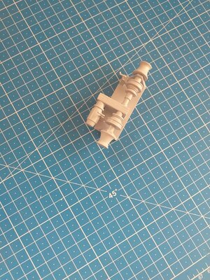
I was surprised to find that they have supplied turned brass fittings to put this together. It is a pretty simple design, but in real life it is only pulling in nets etc, so I guess a trawler probably had a simple winch. It goes together very easily, some laser-cut sheet, a few hand-cut pieces (white glued), and the brass bits (CA glued), and then painted. The brass will need some aging, but I’ll leave that until everything is put together at the end of the build.

1711775526402.jpeg

1711775543045.jpeg

A tip
Here’s a simple tip (the experienced can skip this…maybe). The kit comes with many fittings. And, although there is a listing, I found errors in both the list and the numbering of the fittings on the plan drawings. I’d advise separating all parts into separate bags according to the area they will eventually be used (wheelhouse, rear mast, forward mast etc)…this takes some time to get the correct fittings and sizes or similar objects arranged, but it reduces the chance of using parts in the incorrect places and subsequent re-work.
 
Small Deck Objects
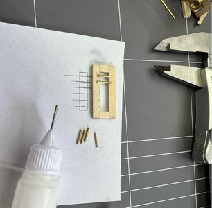
There are a range of small objects to be made up from cut ply. Although the instructions are scant, some of these show as having wire protection overhead, presumably they are skylights for the fishermen working inside the hull. So, I made those up with 1mm brass wire. Later, after painting, I used canopy glue to add some diffused plastic sheeting underneath these bars so that you don’t see the deck underneath. In the case of the one shown below (it goes in front of the main mast), I’ll be added an LED underneath to show a light glow from below at night.

1711775847208.jpeg

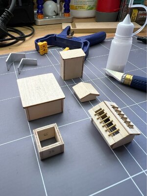
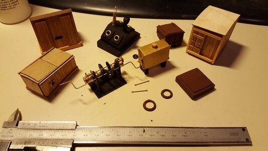
Here is a selection of objects before painting. I’ve been using pieces of aluminium angle to help keep everything square during gluing. I tend to build two lots of right-angled walls and then, when dry, glue those two lots together…rather than trying to get four walls to glue together squarely all at once…

1711775894303.jpeg

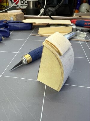
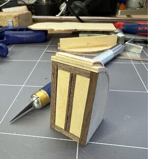
The building below (I’m not sure if it is a companion way down to the hold or just storage, it sits up in front of the main mast) was my first attempt at bending some timber against its will…and it's ply. I did use some hot water soaking, but as others have advised, you need to be careful not to delaminate the ply.

1711775963934.jpeg

The Billing drawings don’t show any detailing of the front, but the online photos of their box-front model does show some panelling, so I added similar. I’ll put some fittings (hinge, door handle etc) on after painting…

1711775997532.jpeg

Next time I'll show you what I'm doing for the lighting.
 
Small Deck Objects
There are a range of small objects to be made up from cut ply. Although the instructions are scant, some of these show as having wire protection overhead, presumably they are skylights for the fishermen working inside the hull. So, I made those up with 1mm brass wire. Later, after painting, I used canopy glue to add some diffused plastic sheeting underneath these bars so that you don’t see the deck underneath. In the case of the one shown below (it goes in front of the main mast), I’ll be added an LED underneath to show a light glow from below at night.

View attachment 438355

Here is a selection of objects before painting. I’ve been using pieces of aluminium angle to help keep everything square during gluing. I tend to build two lots of right-angled walls and then, when dry, glue those two lots together…rather than trying to get four walls to glue together squarely all at once…

View attachment 438356

The building below (I’m not sure if it is a companion way down to the hold or just storage, it sits up in front of the main mast) was my first attempt at bending some timber against its will…and it's ply. I did use some hot water soaking, but as others have advised, you need to be careful not to delaminate the ply.

View attachment 438357

The Billing drawings don’t show any detailing of the front, but the online photos of their box-front model does show some panelling, so I added similar. I’ll put some fittings (hinge, door handle etc) on after painting…

View attachment 438358

Next time I'll show you what I'm doing for the lighting.
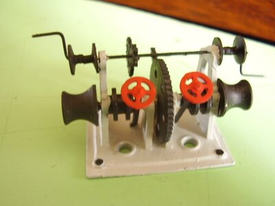
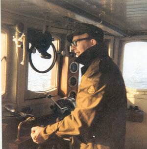
As I have mentioned before, I was brought up my first 16 Years between these types of cutters, and in fact, the main difference between one and another is the fishing gear (tools) depending mainly on which type of catch (fish). The small winches up to bigger, some going forward others sideward etc. Now at the age of 80 nearly (6 months) I have still a huge amount of images of these tools, so if you need info and help just shout.
ps.I was working later on in Esbjerg a few miles from where Billing Boat started and new the Gran old man EJNAR BILLING

billing.jpg

DETAILS.jpg

95.jpg

WINCH.jpg

89587154_10158594420826189_4360205267950895104_o.jpg

89328167_10158594421226189_1141178806321545216_o.jpg

WINCH AND OTHER DETAILS.jpg

WINCH 2.jpg
 
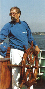
Thanks El Capi, it's always interesting to see other people's interpretation of the design. As I said earlier, I'm keen to have a go at carving some fish for the trays as you've done. And I thought that first photo might have been you captaining one of the boats, but then I realised that it is Mr Billing himself.

thanks
Pete
 
Lighting
The kit comes with nicely machined brass lanterns for the navigational and trawl lights, but there is no actual lighting included with the kit to make use of these nice features, but as I’m regularly playing with small LEDs on various other projects, I can’t resist adding some light and colour to this project as well.

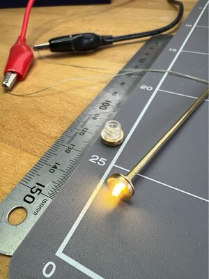
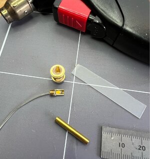
The LEDs I’ll be using are very small (1206 size, they’re about 1.5 x 3mm) and fortunately come with leads already soldered on using very fine tinned wire with a thin clear insulation, so the wires are nearly invisible on the model, before hiding or painting them.

For those of you who are interested…these are warm white and only emit in the front facing direction. They have a forward voltage of 3.3V, and I plan to run them at 12ma as I don’t need full brightness and I think it will look closer to the real thing if they are not too bright. The lights for the boat (around 10, all the same type of LED) will be on two circuits (one forward, and one for the wheelhouse & stern), using a single switch-mode regulator set at 4.5V as it suits the single 100 ohm ½ watt resistor of each circuit, dropping the voltage to around 3.1V and 12ma at the LEDs.

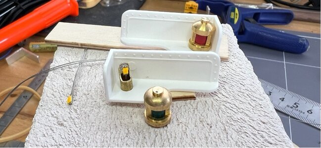
The side nav lights, shown below, are supplied with some coloured plastic sheet that can be curled and inserted to look like the red & green lens of the real thing. I’ve then made up some simple LED lamp holders using some push-fit sized brass tubing. This means that the LED is held securely and facing the right way (they are hot-glued in the removable holder) but can be easily removed from the lantern itself if they need any attention. The brass lantern just slips over the top and will be secured with a minimum of glue in case it needs to be removed later…
1712467034514.jpeg

The brass lantern tops will need some aging at some point, and the backing boards will be painted black. I’ll take some photos with them running after they are installed.
 
More Lights
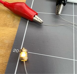
There is also a front trawl light, different in design to the nav lights. As supplied, the brass fitting and lens do not have room for an LED, and it sits on a 2mm wooden dowel post. I’ve changed the post to 2mm brass tube to be able to run the leads to below the deck, and altered the brass fittings slightly to allow the LED to fit. The lower brass fitting has simply been inverted…which to my eye actually looks better as it looks as though the light has a lower flange to connect to the pipe (which you would expect in this application), and I filed off the locating pin from under the upper brass fitting. This means the brass and lens components have to be glued together (I’ve used PVA around the lens so it can be dissolved if needed).

Here it is running, but before the lens and top are glued on. The warm white should look quite realistic to the period of the boat.

1712467201711.jpeg

There are also a couple of lights up on the main mast…a forward nav light (white) and a couple of trawl lights (also white). I’m not sure if I’ll put LEDs in all of them, maybe just the larger ones. The wires will be visible running up the mast for these, but I’ll try to minimise this as they will be running in parallel (electrically speaking) and can be wired from one to the other at the top of the mast.

Below is the forward nav light. I had to make up the lens for this (nothing supplied), it’s a piece of plastic with a rough surface that I had left over from another project. Cut to size and heated to get it to curl enough and pop it in. This also shows the lamp holder technique using a piece of brass tube with a suitably cut aperture that the LED is hot-melt glued to before press fit into the lantern…

1712467383295.jpeg

1712467402528.jpeg

That’s it for the lights for the moment, more later when I hook them up in the boat.
 
As I have mentioned before, I was brought up my first 16 Years between these types of cutters, and in fact, the main difference between one and another is the fishing gear (tools) depending mainly on which type of catch (fish). The small winches up to bigger, some going forward others sideward etc. Now at the age of 80 nearly (6 months) I have still a huge amount of images of these tools, so if you need info and help just shout.
ps.I was working later on in Esbjerg a few miles from where Billing Boat started and new the Gran old man EJNAR BILLING

View attachment 438365

View attachment 438366

View attachment 438367

View attachment 438368

View attachment 438369

View attachment 438370

View attachment 438371

View attachment 438372

MHV_ 06_RORBGAENGER.jpg
 
Hey El Capi that's a great photo! And, believe it or not...I'm about the describe the building of the wheelhouse, so that was perfect timing!

The Wheelhouse
In the absence of any directions on how to construct this, I plan to build each wall, door & roof section as flat panels and then finish them (paint etc) except for the window ‘glass’, then assemble it together on the floor plate. I think it will be much easier finishing things as a flat panel rather than constantly working around and inside a built structure. I also plan to make the roof removeable (with some work, ie screws) in case I need to get inside there in future. There will probably be some touching up of the paint required at the end of the process, but that’s okay.

The standard kit is supplied with a drawing that shows how the 2mm ply panels should be marked up with a pen to replicate the effect of a structure built from vertical planks…even the window frames are just drawn on the ply. Then the ply is to be stained to look like timber.

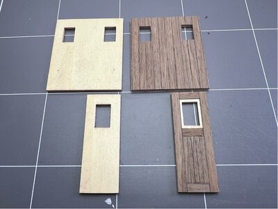
Although I like the strength of the plywood, I’m not excited by the faux planking, particularly for the window frames. So, a visit to the local hobby shop provided me with a bundle of 5 x 0.4mm walnut veneer - I would have preferred something a little warmer in colour but the range is slim for this sort of thing if you want it now rather than waiting for delivery.

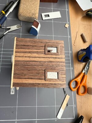
That has allowed me to plank the outside of the wheelhouse panels, and one internal wall, and I think it looks quite good with a clear matt poly finish. Prior to gluing, the edges of the veneer planks were marked with a black Sharpie to give greater definition of the planks.

1712900234390.jpeg

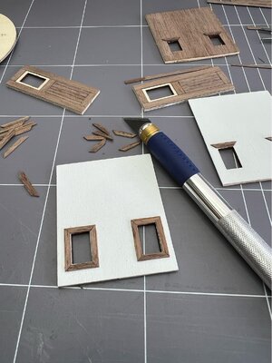
For the window frames I wanted something that stands slightly proud of the walls like the real thing, but I didn’t want to make it look too heavy, or to reduce the size of the windows by applying frames to the inner edges of the window openings. So, I glued two of the veneer planks together to make them a little thicker, then sliced them lengthwise with a knife, giving a timber that matched the planking but was now roughly 2 x 1mm. This was then cut to make simple mitred frames on the internal and external surfaces around the windows.

1712900309319.jpeg

The light coloured ply on the inner edge of the window openings will be painted in a dark wood grain colour.

1712900380609.jpeg

Next time we'll have a look at the curved front wall.
 
Hey El Capi that's a great photo! And, believe it or not...I'm about the describe the building of the wheelhouse, so that was perfect timing!

The Wheelhouse
In the absence of any directions on how to construct this, I plan to build each wall, door & roof section as flat panels and then finish them (paint etc) except for the window ‘glass’, then assemble it together on the floor plate. I think it will be much easier finishing things as a flat panel rather than constantly working around and inside a built structure. I also plan to make the roof removeable (with some work, ie screws) in case I need to get inside there in future. There will probably be some touching up of the paint required at the end of the process, but that’s okay.

The standard kit is supplied with a drawing that shows how the 2mm ply panels should be marked up with a pen to replicate the effect of a structure built from vertical planks…even the window frames are just drawn on the ply. Then the ply is to be stained to look like timber.

Although I like the strength of the plywood, I’m not excited by the faux planking, particularly for the window frames. So, a visit to the local hobby shop provided me with a bundle of 5 x 0.4mm walnut veneer - I would have preferred something a little warmer in colour but the range is slim for this sort of thing if you want it now rather than waiting for delivery.

That has allowed me to plank the outside of the wheelhouse panels, and one internal wall, and I think it looks quite good with a clear matt poly finish. Prior to gluing, the edges of the veneer planks were marked with a black Sharpie to give greater definition of the planks.

View attachment 441193

For the window frames I wanted something that stands slightly proud of the walls like the real thing, but I didn’t want to make it look too heavy, or to reduce the size of the windows by applying frames to the inner edges of the window openings. So, I glued two of the veneer planks together to make them a little thicker, then sliced them lengthwise with a knife, giving a timber that matched the planking but was now roughly 2 x 1mm. This was then cut to make simple mitred frames on the internal and external surfaces around the windows.

View attachment 441194

The light coloured ply on the inner edge of the window openings will be painted in a dark wood grain colour.

View attachment 441195

Next time we'll have a look at the curved front wall.
TO ME IT LOOKS GREAT. YOU DID A DGOOD CHOICE TO CHANGE THRE PLYWOOD
Hey El Capi that's a great photo! And, believe it or not...I'm about the describe the building of the wheelhouse, so that was perfect timing!

The Wheelhouse
In the absence of any directions on how to construct this, I plan to build each wall, door & roof section as flat panels and then finish them (paint etc) except for the window ‘glass’, then assemble it together on the floor plate. I think it will be much easier finishing things as a flat panel rather than constantly working around and inside a built structure. I also plan to make the roof removeable (with some work, ie screws) in case I need to get inside there in future. There will probably be some touching up of the paint required at the end of the process, but that’s okay.

The standard kit is supplied with a drawing that shows how the 2mm ply panels should be marked up with a pen to replicate the effect of a structure built from vertical planks…even the window frames are just drawn on the ply. Then the ply is to be stained to look like timber.

Although I like the strength of the plywood, I’m not excited by the faux planking, particularly for the window frames. So, a visit to the local hobby shop provided me with a bundle of 5 x 0.4mm walnut veneer - I would have preferred something a little warmer in colour but the range is slim for this sort of thing if you want it now rather than waiting for delivery.

That has allowed me to plank the outside of the wheelhouse panels, and one internal wall, and I think it looks quite good with a clear matt poly finish. Prior to gluing, the edges of the veneer planks were marked with a black Sharpie to give greater definition of the planks.

View attachment 441193

For the window frames I wanted something that stands slightly proud of the walls like the real thing, but I didn’t want to make it look too heavy, or to reduce the size of the windows by applying frames to the inner edges of the window openings. So, I glued two of the veneer planks together to make them a little thicker, then sliced them lengthwise with a knife, giving a timber that matched the planking but was now roughly 2 x 1mm. This was then cut to make simple mitred frames on the internal and external surfaces around the windows.

View attachment 441194

The light coloured ply on the inner edge of the window openings will be painted in a dark wood grain colour.

View attachment 441195

Next time we'll have a look at the curved front wall.
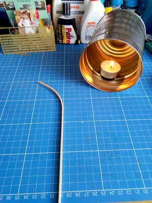
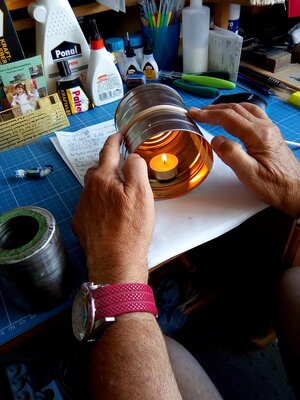
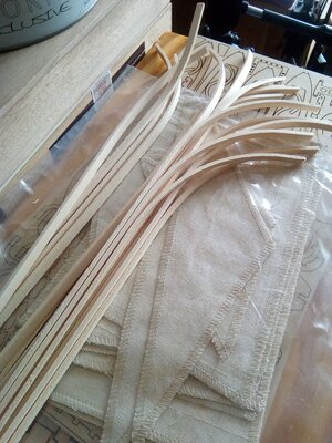
IT IS NOT THAT DIFFICULT. USE THE GERMAN HOT METHODE- DESCRIBED SOMEWHERE, BUT IT CONSIST OD FINDING A TIN CAN -MORE AND LESS THE SEIZE YOU WANT TO CURVED-INSIDE YOTSET SOME CANDLELIGHT (THE CHINESE TYPE. BE SURE THE TIN IS FASTENED VERY WELL, AS IT IS EXTREMLY HOT.A COMBINATION OF A SHORT TIME ON STEAM(KITCHEN) WHEN THE FROM STEEM COMES IN CONTACR WITH THE HOT TIN CAN, THE TEMP WILE RISE VERY MUCH- WHAT WE NEED.

05-bending woods-132.jpg

05-bending woods-133.jpg

05-bending woods-134.jpg
 
Back
Top