Build Log: Falconet 1:48 Imperial Yacht Uvalen

Joined
Nov 4, 2021
Messages
301
Points
168

I'm really leaving my comfort zone starting a build log because 1) I've never done a build log, 2) I've never been able to complete any wooden ship ever started (other than some small boats in the novice category), 3) I expect to get chewed out a lot for not using the right terminology for parts and processes, and 4) this is probably more for my benefit than anyone else's as I can see I'm going to need a lot of help with this. With that said, part of my motivation for doing this build log is to share what I learn of this kit as I go along because I gather not too many have tackled this relatively new offering.

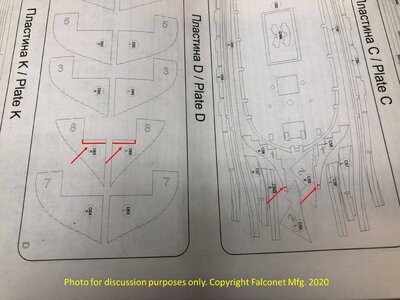
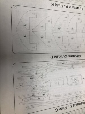
My first observation about this kit is that the fit of the parts so far has been, with few exceptions, excellent. The laser etched fairing lines on the bulkheads really are a great help. Laser etching part numbers into the larger parts would have also been a great help, especially since some parts are mislabeled (In the instructions there is a part A10 on each of the plates labeled "Plate A (part1)" but one of them is really A11. I will also say the instructions are pretty sparse for words, and it takes a great deal of studying the pictures, referencing back and forth, and imagination to figure out what one is really meant to do--I suspect having more experience than I have with ship building would mitigate much of that--but so far I'm figuring things out without any irretrievable errors that I have detected.

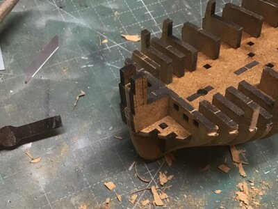
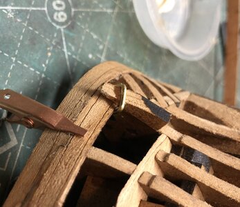
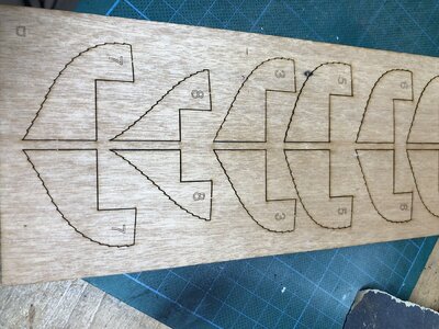
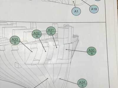
Assembling the bulkheads went pretty quickly due to the precise fit. Ran into a snag in step 3 when I discovered parts A30R and A30L were much taller than they appeared in the assembly instructions:
Uvalen1.jpg
Uvalen2.jpg
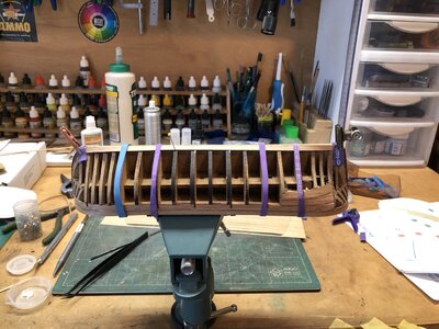
It was only as I got ready to start planking that I realized that those parts, like all the stanchions on the bulkheads, get cut of flush with the sub-deck once the wales go on. Problem solved, but it was a head-scratcher for a while.

The next surprise came as I started working on the wales which, along with the sub-deck and a few other parts come from plate C. Since these need to follow fairly substantial curves around the bow and stern I figured they would be a good place to try my hand at plank-bending. It was at that point I discovered plate C is not actually a solid 1mm piece of wood, but two 0.5mm sheets laminated together like plywood (but with the grain of both pieces aligned with one another). The moisture and heat of trying to bend these parts caused them to delaminate, requiring me to glue them back together again and let that sit until the glue dried before I could mount them.

In steps A5 and A6, you assemble two bulkhead assemblies, which if you are paying careful attention in step 8, you realize are just there to help form the wales and do not get glued to the hull. Subassembly 5 has two tabs that fit into two slots in the sub-deck, which is a somewhat loose fit, and as I moved the model around working on the planking the it kept falling out. Solution: drilled a couple holes through the tabs right underneath the sub-deck and inserted a couple of pieces of toothpick. Rock solid now, but easily removed when the time comes.

Hopefully some progress photos next time.
 
Last edited:
Try doing a search under the kit name and you may find other build logs or comments about this kit.

And your doing the right thing showing and telling what your question is, the folks here normally offer great help.
 
LOL. I actually found this site because it was the only one that came up when I did a search for that kit in order to solve the problem I was having originally. If anyone else is building this kit they don’t seem to be blogging about it.

BTW, I’m a regular on Kitmaker Network, but that’s mostly plastic.
 
Last edited:
Many Thnaks for starting your building log of this interesting model.
The Uvalen kit from Falconet is relatively new and was released just one year ago, so it is in principle very hard to find building logs in such a "short" time......


We are happy to host such a building log in our forum .....
 
Try doing a search under the kit name and you may find other build logs or comments about this kit.

And your doing the right thing showing and telling what your question is, the folks here normally offer great help.
I have to ask, @Kurt Konrath , if you are/were a HawHAWG Driver. one of the most beautiful planes ever built IMHO
 
Last edited:
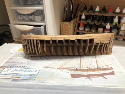
Still futzing around with getting bulwark planking correct. I have a set of planking clamps, but I was concerned the "micro-screws" would just split the thin MDF the bulkheads are made from. So I made a little horseshoe from brass rod and left the ends sharp where I cut it. The sharp ends bite into the sides of the bulkhead and then I can push a small wedge into it to press the plank into place:

IMG_1378.JPG
Seems to work okay. Would prefer to use something springier than brass, but I'm afraid something as hard as stainless steel would damage my tools.
 
Last edited:
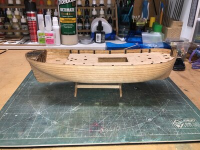
Continuing along, the under-planking is done and I'm ready to start planking in earnest.
IMG_1382.JPG
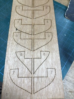
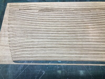
Falconet has taken pity on newbs like me, and instead of having me fair a bunch of steps for this clinker-hulled ship, they have provided some 1mm thick planking steps that laminate to the frames:
IMG_1379.JPG
I learned right away that the part numbering in the instructions is a bit mixed up so instead of following those, I went off the large numbers printed on the parts themselves. They install starting at the stern with number 1 and working forward to number 8 at the bow.

I also discovered parts 1 and 8 need to be trimmed slightly in order to fit:
Picture1.jpg
Am somewhat daunted by my first attempt and hull planking, but I'm keeping my fingers crossed that clinker construction is more forgiving than carvel planking.

Beer

IMG_1379.JPG

IMG_1381.JPG
 
Another update, not because I have made much progress, but because I have a question I'm hoping someone with experience in clinker planking can answer.

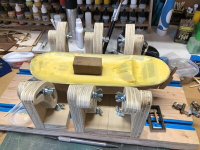
I trimmed up a scrap of Ipe to fit snuggly in the cabin well, which allows me to easily clamp the hole thing into my swivel vice, plus I can easily pop the model off to swap ends and work on the opposite side. This made things much easier getting both garboards laid down.
IMG_1387.JPG

One thing I've learned during the process of laying down the garboards is that those plank alignment battens I mentioned in my previous post are really not all that helpful. They don't fit the frame as accurately as they need to in order to guarantee alignment. The result is that they only need to be off by a hairs-breadth to really mess things up. Only a couple of them ended up close enough to work. The rest I'm having to shave off as I go. I'm only taking them off a bit at a time as I think they will still have some utility as indices as the planking progresses.

So here's the question for the group: All hull planks except the garboards have a marking line scribed in them, which, if the instructions are correct, would be on the outboard (visible) side of the plank. Unlike the bulkheads and false keel, there is nothing in the instructions to indicate this is telling me to chamfer the edges, nor does it seem like on clinker-built hull would you want the lower edge of the plank chamfered anyway. If the instructions have the sides flip-flopped (as had happened with a couple of other pieces) then the markings are on the inboard side where they can't be seen.
IMG_1388.JPG
Anyone have any ideas what those lines are for?

I'll close by thanking everyone who has been stopping by to look at my build. It's not nearly as impressive as most builds on the site, but I'm having fun sharing.
 
Last edited:
Just a wild guess, but could that line indicate the overlap expected from the plank above it? Regarding your initial post, I can't believe you would get criticized by anyone here if you or I use the "civilian" term for some piece of ship hardware or rigging. We might learn the correct term in passing. I did a build log here of my first model (a modest plank on bulkhead kit) and it was a good experience. Nothing but positive feedback and advice. And your experience sharing is appreciated by all.
 
Thank you, TangoPapa. I appreciate your feedback. Your suggestion prompted me to go back and look at the photos in the Uvalen New Release Announcement to see if there really was that much overlap. Although the photos confirm they don't overlap that much, they do show those lines are clearly visible on the planks.

So thank you for leading me to the answer!
 
Last edited:
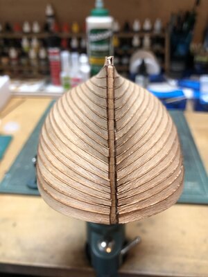
Finally finished with the hull planking.
78CAA2A6-CC14-499F-BE62-70821F4E471B.jpeg
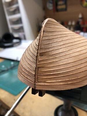
The laser cut planks fit flawlessly, but the process was a bit tedious because I just could not figure out a way to precisely hold the ends of the planks in place while the glue dried other than the Mk1 Mod0 Finger.

Another thing that gave me some trouble was that because only the midships planking battens fit precisely enough to be useable I had to start by securing the midships portion of the plank and working slowly fore and after to lay it down to the hull. This in turn meant I had to get the plank correctly positioned laterally from the start. As you can see, I was able to get close for the most part, but not perfect.
64197040-2BA6-4738-8B67-C85028BE1BCA.jpeg
I was also unable to figure out definitively whether the planks should sit flat to the frames on the ends or overlap, as the do for the length of the hull. Laying flat would seem to fair to the keel bevel better, but that tended to leave some gaps and it was clear that approach would prevent some planks from aligning with the guidelines on the bevel.
1D1934B3-9989-4A92-B454-68A7EA235047.jpeg
In the end it turned out some planks tended to lay flat and some tended to overlap, so I did whatever was needed to keep them as close to the guidelines as possible, knowing that if that got off track it would have a compounding effect on subsequent strakes. I’ll just have to go slow and easy smoothing the, down and fairing them into the cutwater and sternpost.

In order to make up for any inaccuracies in beveling the false keel, I had to assemble the cutwater, keel and sternpost prior to installing the false keel bevel. That was necessary to ensure the final shape of the bevel would fit the keel assembly perfectly with out any gaps in the joinery. So next I start fairing the ends of the planks and install the keel assembly.

Now a question for the group on finish. I had been toying with idea of leaving the hull a natural wood finish, but my problem with the plank ends have convinced me that it will need to be painted. I plan to give the hull a coat of latex sanding sealer to protect everything and help me get a nice smooth finish before painting unless some knows of a reason this would be a bad idea. Then I have to figure out how to get a nice clean paint line between the upper white portion of the hull and the lower red portion. Using a waterline gage to mark the line is easy enough, but as for painting I’m still scratching my head. If it were a smooth hull, I would simply mask of an all-white hull and then airbrush the red on. But with the clinker construction, I afraid trying to mask the waterline will be an exercise in frustration and leave gaps for overspray to get in. Anyone have any good ideas?
 
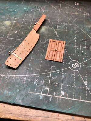
Very small update after very slow progress. Trying to get things prepped to paint the hull, which, counterintuitively, requires a lot of deck and cockpit work to be done first. Among other things, I got the rudder prepped to install (that will be last to go on before painting to minimize the chance of breaking the hardware) and the companionway door. I can see from the photo I’ve still got a bit of glue to be cleaned up on the rudder.
D0328CE3-BA99-471A-A81F-63FC88C95628.jpeg
The kit doesn’t include doorknobs, but I felt some where necessary so I tried to make a couple from pieces of 1mm brass rod. Not sure if knobs are historically accurate compared to some other kind of handle, but the Falconet photos of the completed kit feature them so that’s what I’m going with.
 
Last edited:
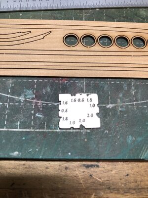
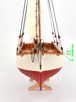
Soon I have to add the molding around the top of the bulwark. Falconet provides this nifty little profile shaper, but gives no clue in the instructions as to which profile is for which part. The numbers on the plate are presumably some kind of dimension (whether it is width or depth is not immediately apparent) and do not correspond to anything I have found in the instructions
4B16FD6E-BEE9-4B3E-B5C9-2988B665F570.jpeg
I have at least been able to figure out that the profiles marked 1.6 are for the bulwark moldings (parts J110 in step 18)…or so I hope.

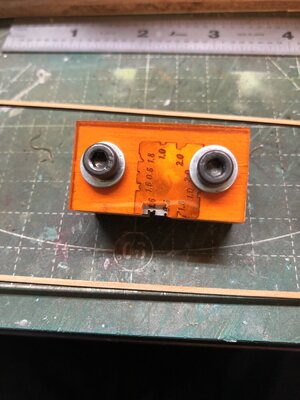
In order to keep the scraper square to the workpiece I sandwiched it between a block of plywood and a scrap of acrylic
D41721D7-CA90-42F0-9A0B-3D2FAD0008F1.jpeg
 
Last edited:
Back
Top