HMS Snake

Thanks for the offer, Gary. See the photo below, they are described as 'side fenders' but not shown on any side profile plan. The hole in them is pre-drilled and my guess is that it is something to do with a rigging attachment, but is the only pre-drilled hole in the entire kit if it is related to rigging - I have scoured the rigging plans for a likely culprit, but no joy. Any ideas welcome.

PHOTO CAN NOT BE FOUND FOR RELOAD
 

Attachments

  • Side Fenders.JPG
    44.2 KB · Views: 1,139
Just finished up the chainplates and put the capping edge on the channels. I pre-painted the parts which pin to the hull but not the rest. All is painted matt black and I found it necessary to have a good look at them all again in daylight the next day from a few angles – some touch-up was necessary and brass does not always cover well on only one coat.
You will see that there is an additional ‘piece’ between the links on the longer chainlinks and the simple fact is that the top plank of the wale is fitted too low – it is OK at the bow and stern, but drops down in the middle. I can’t believe I didn’t measure it from the plans and made this stupid mistake. Having thoroughly beaten myself up the options I considered were:-
a. Rip the wale off and re-fit it again – forget it.
b. Add additional planks to the top of the wale – I held a couple in place but it looks very clunky, so no.
c. Make another link from 0.5mm wire – tried it, but getting a consistent shape and a tight enough bend on both ends of the link is very difficult.
d. Use cord - which I did.
On the good side the problem is the same on both sides of the ship distance-wise, so at least it’s a consistent cock-up. Anyway it is what it is and people who look at it won’t know, but I will always see it – the curse of the modeller, I guess. It won’t happen on the next build and I detail it here for the benefit of other new builders as something to watch out for.
 

Attachments

  • Main Chains 1.JPG
    Main Chains 1.JPG
    63.8 KB · Views: 140
Hi Graham, another option to your "c" is to make two slightly smaller links. If they are too small to handle make a 'jig' from a hacksaw blade or something (not knowing the size). Also shouldn't the chain link be closed?
Regards
Eric
 
Hi Eric. I thought the chain links should be closed as well, but if you press it such that the open ends meet then it buckles outwards. What you see is how they are. I have looked at photos of other completed JoTika kits (including Agamemnon) and they are also open, so I don't know. Perhaps some thin tubing slotted over might look better, but you're talking something like a hypodermic needle at this scale - not the easiest thing to buy!
 
Fenders were used on the side of a boat to absorb the effect of bumping into objects, especially when docking a boat or when tied up to a pier. They were on the side of a ship. Rope was originally used for this shock absorption or an object that would stop damage to the main surface. With the invention of foam and then plastic, modern era vessels use this material. The reference below describes more:
https://en.wikipedia.org/wiki/Fender_%28boating%29
 
Thanks Gary. I know what a fender is, it's where to place it on the hull. Somewhere along the widest part of the hull seems logical, but it does not look right wherever I offer it up. Regards.
 
I haven’t done anything on the ship for a month due to a garden project which needed completing, but finally got some time in. Time to sort out the Carronades. As I said in an earlier post I have received substitute brass carronades, although they are a different fitting. Here’s what I did to utilise the new barrels and rig the guns:-
a. Using the existing trunnion brackets, thread them on a cocktail stick (which was spot on for size) and check the spacings between them against the slots in the carriage, CA glue them on the stick -


b. Cut off the cocktail stick either side of the trunnion -


You end up with a solid mounting –


c. Trial fit on the carriage and CA glue the trunnion to the barrel when happy with the angle. I found I needed to grind off quite a bit on the bottom of the trunnions or else the top of the gun barrel fouls on the gunport. The photo is prior to this grinding and hence the barrel is not yet horizontal –


d. Barrels painted in semi matt and colour washed (watered brown acrylic) to give some definition –


e. Tied on the recoil ropes prior to fixing the barrels to the carriages –
 

Attachments

  • Carronade 4.JPG
    Carronade 4.JPG
    57.2 KB · Views: 135
  • Carronade 5.JPG
    Carronade 5.JPG
    36.7 KB · Views: 136
  • Carronade 6.JPG
    Carronade 6.JPG
    17.2 KB · Views: 138
  • Carronade 7.JPG
    Carronade 7.JPG
    42.3 KB · Views: 140
  • Carronade 8.JPG
    Carronade 8.JPG
    61 KB · Views: 139
  • Carronade 9.JPG
    Carronade 9.JPG
    65.6 KB · Views: 136
f. All guns as rigged so far –


I am awaiting the Postman with some more pulley blocks to finally rig the gear which pulls the carriage to either side for loading and will drop in a photo when complete. You will see that I have tied the recoil rope on top of the barrel, as per the photo I am basing the rigging on – I quite like the neat look of it.


At this point I built a mock-up of the gun port to do the rigging rather than fumbling about on the actual model 18 times and breaking things. This allowed me to easily get tweezers in (not to mention my fingers) to rig the pulley blocks –


I left the eyed pins long then bent them over once passed through the bulwark; when rigging is done simply cut them off and they are to the correct length for fixing on the model when the time comes. Now that I am happy the barrels are horizontal I have reversed the elevation screw so that the screw head is recessed under the carriage.

I may tie the loose cord ends off around the pulley blocks as per the photo I am working from. However, I see some modellers coil them on the deck. Given the spacing between these guns that may look a bit cluttered but I’d like to think about it. Does anyone have a quick and easy method they can share for coiling rope on the deck and keeping it in place? Coat it with PVA – but does that change the cord colour i.e. darken it? I can see the twist of the cord causing a problem which others must have overcome. Cheers.
 

Attachments

  • Carronade 10.JPG
    Carronade 10.JPG
    38.9 KB · Views: 126
  • Carronade 11.JPG
    Carronade 11.JPG
    58.3 KB · Views: 126
  • Carronade 12.JPG
    Carronade 12.JPG
    31 KB · Views: 126
Very nice work. Should not have been that hard and the kit should have showed the right way to do everything. I useTight Bond translucent glue on the deck and wrap it in place that way. Then the top of the rope does not change color or show that glue was used.
 
Thanks Gary. In fairness when they sent me the new barrels they did say that the mountings and carriages were now different, so I knew I'd be in for a bit of improvisation and fettling! Your tip on coiling the rope is appreciated, I'll do a test or two to get the hang of that; cheers.
 
Hi Graham, them cannons are looking really good, you've done a great job with the rope work, I think that method of coiling is one for me to remember when I get to that stage.
keep up the good posts.
 
A few photos to post so I’ll split this entry up a bit – not sure on how many per post. The pulley blocks to rig the gear which pulls the carriage to either side for loading have arrived, so we can crack on and I tied the blocks on the carriage to 2mm rings -


Top tip – when tightening a knot onto a pulley make the first turn of the knot on the pulley, then hold the pulley behind your front teeth and finish the knot. Just don’t tighten it onto your moustache as I did several times or you will be creating a new fashion look which, my wife advises me, is not a good one.

I pre-drilled the bulkheads to take all the fittings; I drilled them all at the same time to be rid of the dust.


Learning point – I should have waited to fit the higher deck fittings (companionway, wheel, pin rails) because they get in the way of drilling the holes – just glad I haven’t fitted the ladders yet. I shall curb my enthusiasm next time and ignore the instructions.

Cannon dropped into place and front location pin fitted -


Recoil rope eyelets glued to the bulkhead -


Run out pulleys fixed to the bulkhead -


Then side to side pulleys -


Learning point – after some frustration I found it best to work a couple of guns at a time because it gives the CA glue time to set well in the bulkhead whilst you go back to working on the other gun.
 

Attachments

  • Carronade 14.JPG
    Carronade 14.JPG
    46.3 KB · Views: 102
  • Carronade 15.JPG
    Carronade 15.JPG
    82.6 KB · Views: 102
  • Carronade 16.JPG
    Carronade 16.JPG
    57.2 KB · Views: 102
  • Carronade 17.JPG
    Carronade 17.JPG
    46.2 KB · Views: 101
  • Carronade 18.JPG
    Carronade 18.JPG
    35.5 KB · Views: 103
  • Carronade 19.JPG
    Carronade 19.JPG
    53.1 KB · Views: 103
When tensioning the pulley ropes the cannon was too wobbly and I ran out of fingers, so I put a brass pin through into the deck because gluing the rear wheels to the deck did not work very well -


I will touch the pin up in the same red as the carriages later. Ropes tensioned and tied off -
 

Attachments

  • Carronade 20.JPG
    Carronade 20.JPG
    39.5 KB · Views: 97
  • Carronade 21.JPG
    Carronade 21.JPG
    45.1 KB · Views: 97
One side of the ship is now complete and making the mockup to do the bulk of the rigging off the ship was certainly worth it. I will try and make coils on the deck of the longer ends shown in the photos, but if it all goes wrong I’ll simply tie them off. I’ll drop in a couple of photos of the completed deck when done. Cheers.
 

Attachments

  • Carronade 22.JPG
    Carronade 22.JPG
    34.3 KB · Views: 101
  • Carronade 23.JPG
    Carronade 23.JPG
    63.1 KB · Views: 104
A broadside from this ship would have been devastating, the point blank range for a 32 pounder cannon is/was 300 yards. Assuming these guns had the same range and all nine guns scored a hit it would only take a few rounds to tear a ship to shreads.

I have experimented coiling waxed rope, if the beeswax is relatively soft the rope can be coiled in ones fingers, once it has cooled down the coil will hold its shape, however, because it is now waxed it may not stick to the glue. A drawback I have found with waxing thread is that when it is pulled through the wax it will become thinner and perhaps for scale purposes too thin (more suited to rigging).

Like the use of "blue tack" great idea! it would also help keep tension on the ropes.

Regards
Eric
 
eric61 said:
because it is now waxed it may not stick to the glue

Eric hi,

Great job with the guns! :handgestures-thumbup:

For the coils I go like this: make the coil on a suitable diameter pencil. Apply some dullcote lacquer. Once dullcote dries it adds no color or stain and holds very well.

Here's an example ...

Cem.
 

Attachments

  • 03.jpg
    150.8 KB · Views: 773
Thanks for your comments, guys.
Eric - yes, devastating indeed and at short range they would have been 'double shotted'. Being on one of these ships during battle must have been a grim and terrifying experience.
Cem - appreciate the tip on the method you use, cheers.
 
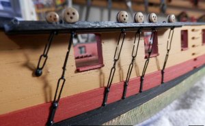
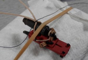
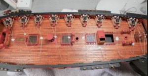
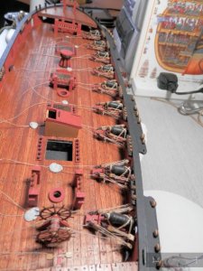
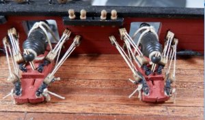
Well, I tried coiling the rope on the deck but could not get the look I wanted and after a couple of hours I lost the will to live, so I made some hanks. After trying several ways here’s the method I used:-
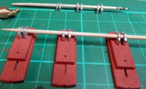
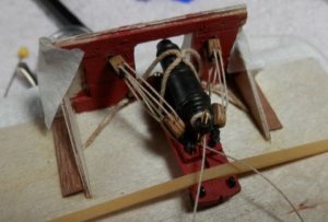
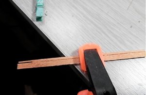
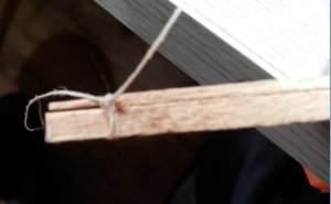
1. Make a jig from a couple of planks (note the slot) and clamp it to the bench.
2. Lay a length of cotton in the slot.
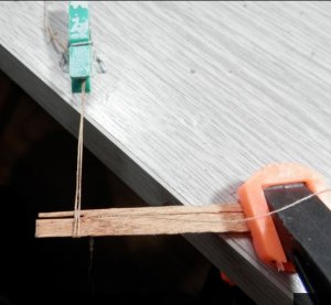
3. Wind the cord around the jig. I found that 3 turns was enough but you could go a few more if you want a bigger hank. Put the ends in a peg blue tack’d to the bench to keep some tension on it.
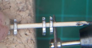
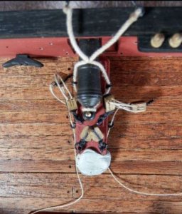
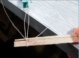
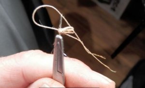
4. Knot the cotton to keep the hank together and trim the ends.
5. Take one of the ends of cord, pass it up through the slot, back down around the hank, back up through the slot and then knot it (reef knot). This secures the hank and also hides the cotton.
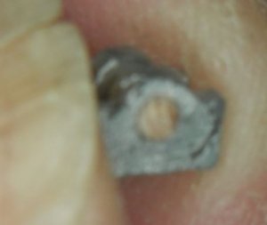
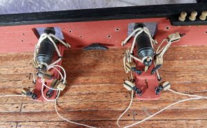
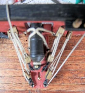
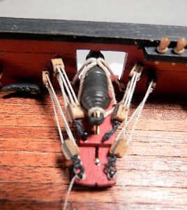
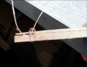
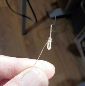
6. Pull the hank off the jig. Use some very fine wire to make a needle threader, push through the top (smaller) loop and pull a cord end through. Cut the end at the back of the hank off at the knot. Trim off the end you pulled through to the length required and ‘mould’ the hank to the desired shape.
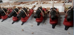
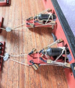
Hope that makes sense. I had a look on the internet but couldn’t find anyone else’s method, but this worked for me so I thought I’d share it. The photos show the sequence.
 

Attachments

  • Hanks 1.JPG
    Hanks 1.JPG
    26 KB · Views: 109
  • Hanks 2.JPG
    Hanks 2.JPG
    42.9 KB · Views: 109
  • Hanks 3.JPG
    Hanks 3.JPG
    47.1 KB · Views: 110
  • Hanks 4.JPG
    Hanks 4.JPG
    34.1 KB · Views: 109
  • Hanks 5.JPG
    Hanks 5.JPG
    24.3 KB · Views: 109
  • Hanks 6.JPG
    Hanks 6.JPG
    26.7 KB · Views: 109
  • Hanks 7.JPG
    Hanks 7.JPG
    22.1 KB · Views: 109
Hanks fixed to the carriages.
 

Attachments

  • Finished Carriage.JPG
    Finished Carriage.JPG
    84.1 KB · Views: 110
Back
Top