CAF HMS Granado by Experten

Joined
Sep 24, 2017
Messages
30
Points
48

Hi All,

I just started my cross section build, and have a puzzling problem.

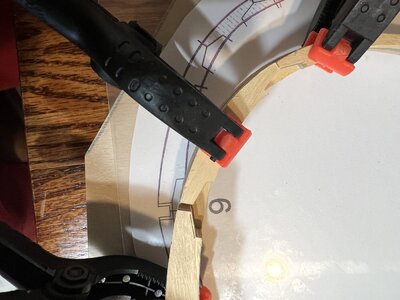
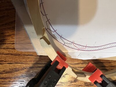
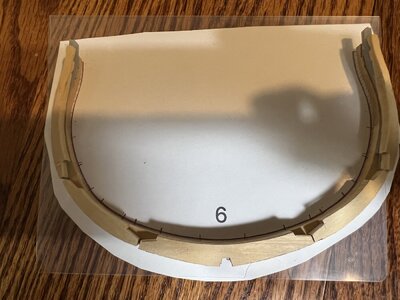
I started with frame 6, and my lower set of frame components matches the drawing perfectly. However, the upper set is leaving HUGE gaps. It’s almost as if the parts were milled undersized.

Any ideas? It’s not a problem I’ve seen in the other logs on this kit..
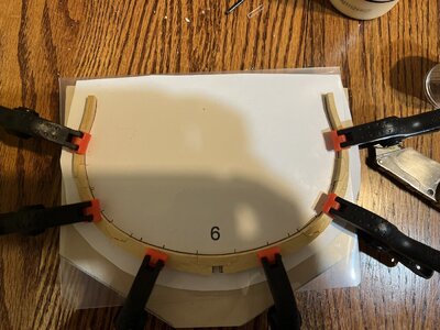
8BFC038B-478C-41B1-AB8D-A70348FC1AD4.jpeg

BC4DF490-AC96-4B8C-9786-3FB763D526B3.jpeg

0872C80E-C52D-48E4-BDDE-4DDB2296590D.jpeg
 
Last edited by a moderator:
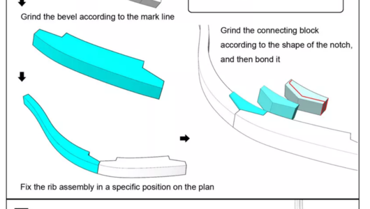
Its not an error, you need to dry fit the frame pieces together, then mark the pieces and sand off the ends with a disc sander to the correct size.
 
The futtock ends have to get into contact and the chocks have to be addjusted.
These chocks are on purpose slightly longer, so that the inidividual modeler can adjust according their needs.
So the parts are on purpose in this way prepared.

Please take a look at my post and the following in my building log of my section, where you can see how I did this at this time

 
I would be happy to see, if you start a building log of your section model project!
Would be great to see and follow - so if necessary we could give further hints for this challenging model
 
Just found also the description on the CAF manual describing this way

Screenshot 2022-09-02 104137.png

So don´t be worry - everything correct
 
Looks like our fellow Granado builders have already answered your query, so would just like to welcome you to the group!

Ted
 
By the way, it seems that this is starting as a build log which is nice - however, I need to change the TITLE to HMS Granado.
 
Hi All,

I’m afraid that I’m still not seeing the solution. The first, assembled layer matches the drawing perfectly. The resin insert for spacing also fits exactly as it should. @Uwek, there’s nothing to sand off, as the parts are too short, which is what confuses me so much. As you might recall, there is almost no bevel to frame 6, so info in the link you so thoughtfully provided doesn’t apply.

A95D530A-08AB-4328-957D-4446B70F7045.jpeg
 
Last edited:
Understood
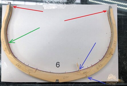
I checked my old photos and found the frame 6 documented - also I had some very small gab and filled it with some 0,5mm of the sheet material (see the blue arrows)
but taking a closer look on your photo you should try to lay the half of the frame on the drawing to check each individual half

IMG-7992.jpg

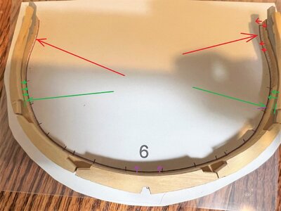
Looking at my red arrows - the ending of the top timber is exactly on the end of the drawing - so the height is matching - looking at your photo the top timber of your lower half of the frame is somehow 1 or 1,5mm higher than the drawing
Also the partare laying not exactly on the drawing, they are moved outwards by 1 or 2mm (red arrows on your drawing)
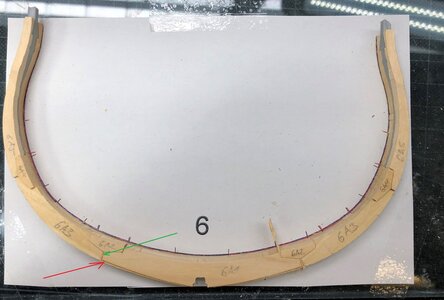
Also the lower end of the top timber (upper half of double frame) is not laying exactly overlapped with the lower half (green arrows)
also the floor timber is slkightly too low (purple)

A95D530A-08AB-4328-957D-4446B70F7045.jpeg

Therefore I suggest, that you lay only half of the frames (6A or 6B) exactly on the drawing - the edge of the wooden part should be exactly on the center of the black lines of the drawing - so only the half of the printed line should be visible
=> you will see that the error with the wedges is much smaller

BTW: I think that you also should turn the half frame elements 6 A by 180° - I can not see any laser marks for the bevelling (red arrow)
Or did you bevel the parts already before you fix them to a complete frame?
IMG-7992a.jpg
 
Back
Top