CAF HMS Granado 1:48 POF

Joined
Jan 14, 2019
Messages
204
Points
143

Location
Pine Valley, CA
Hope all had a Happy Thanksgiving and survived the holiday. Have been working on Part One of this CAF Granado kit for a while now. Part Two is waiting in the wings. Have completed all of the main ribs and have been impressed by the quality of the rib design and of the jig for assembly.
DSCF1020.JPG
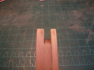
Everything is dry fit at this point as I get ready to tackle the trickier bow and stern rib structures. While checking the fit of the keelson pieces with the installed ribs, I noticed that ribs 8 through 15 sat too high on the keel and were impacting the fit of the forward keelson piece. During initial construction, these ribs require substantial sanding for contour and I was pretty careful to follow the lasered lines provided on each piece to get the contours right. Even so, I had this problem with ribs 8 through 15. Not sure if anyone else has seen this yet. My solution was to carve out a small channel in the inside bottom curve of the rib to accommodate the keelson. Rib 8 had the deepest cut and 15 had the shallowest. Below is rib 8 followed by rib 15
DSCF1017.JPG
Below is rib 15DSCF1018.JPG
By making these mods, the forward keelson piece fits snugly against the top of the keel section at the bow. Not sure if I have bought myself problems down the road but this seems to be working for now. Ribs aft of nr 15 all ride nicely on the keel and the dry fit of the keelson is working well. Rib 9 and rib 44 are loose in the jig (have side to side play of about 5mm). When I checked against the plans, my rib 9 was spot on with the drawings, rib 44 looks to be my bust as it is slightly narrower than the drawing. Will sort that later.

Regarding the split hull issue on this kit, the instructions call for the use of pieces of wire to temporarily hold the upper pieces of the various rib sections in place with the lower sections while assembling the upper section. I have done some dry runs using scrap wood and have not had much luck. What has some promise is the use of railroad track screws which are about the perfect size.
DSCF1021.JPGDSCF1023.JPG
I was able to get these on Amazon but they are carried in a variety of hobby/train shops. As shown on the box, they are 10mm in length and 1.4mm diameter. Phillips head. What I am hoping is that with these mini screws, I am going to get more "bite" in holding the small pieces together temporarily than I would with smooth pieces of wire. In any case, once these screws are removed, will have small holes to fill/dress (would have that issue with wire as well). I am going to try to muster the courage in the next few days to start drilling some holes in the ribs and putting this theory to the test. Would appreciate any comments/thoughts/better way if anyone has opinions to share.

DSCF1019.JPG
 
Wow... looks very well done so far. Thank you for showing the details of a few issues you encounter. It will help all of us.

To my knowledge, @Bryian and you are the first builders. Bryian have decided to glue the ribs. When my time comes, I will try to build it with a split hull, like you. Thank for the screws tip. I will order them.

I have the kit. But will not start to work on it for a while.

I will follow enthusiastically your build.

Best !!
Daniel
 
Last edited:
very nice beginning, I will follow enthusiastically your build.
 
Hello
as I would like to build the caf granado kit I am following this discussion with interest. since I too would like to divide the hull, I am intrigued by the proposed solution. my question is: how do you plan to remove the screws once the ribs are wrapped? P.S. sorry my bad english but i don't know the language
 
Are you planning to clean the carbon from the laser inside the case? Earlier, I assembled the CAF La BELLE kit, and after assembling the case and applying oil, some uncleaned dark spots from carbon deposits were visible, although I expected that they would not be visible after assembly.
 
Hello
as I would like to build the caf granado kit I am following this discussion with interest. since I too would like to divide the hull, I am intrigued by the proposed solution. my question is: how do you plan to remove the screws once the ribs are wrapped? P.S. sorry my bad english but i don't know the language
Looking at the part two directions I think that I will be able to remove the screws once I have installed the reinforcing "wale" on the upper sections of the ribs. That's the early plan anyway By the way, your English is just fine. Thanks for your interest, I will try to post how it goes as I work through the build
 
Are you planning to clean the carbon from the laser inside the case? Earlier, I assembled the CAF La BELLE kit, and after assembling the case and applying oil, some uncleaned dark spots from carbon deposits were visible, although I expected that they would not be visible after assembly.
Great suggestion and now I will. Thanks very much. I will spend a fair amount of time now cleaning up the ribs and the fit in the jig
 
Hello everyone
1:During the production of frame keel, I reserved an allowance of 0.3mm, which is mainly used for grinding carbon black and installation and adjustment
The clamping groove at the bottom of the rib in the middle section is horizontal, so it is easier to adjust
The inclination of the rib groove in the bow part is relatively large, and there will be a lot of work to adjust the height during installation
3.JPG
Adjust the rib height according to the muzzle position height,
In the later stage, all measurement templates are based on the muzzle position

2:If you need to separate the hull up and down, it will be a great challenge
We need to pay attention to these structures
4.jpg
Red internal partition wall and upper girder
They need to be separated as far as possible without adhesion, and a certain gap is required in space
3.JPG

4-1.jpg
The same is true at the tail. The partition wall is close to the upper girder.
4-2.jpg
Of course, you can also cut off the area where the upper part of the partition wall contacts the girder, which will make the separation work very convenient

4-3.jpg
The green line is the upper and lower separation line
4-5.jpg

4-6.jpg
The girder in the yellow area cannot be bonded to the lower hull
 
First of all great, that you started with this interesting model.
I will follow your log with big interest, because I am also planning to make my model with a splitted hull,
but before I am "training" with the Granado section model from CAF...... I just also started my new building log

Very good, that Tom is following the logs of the new kit(s), so we can get assitance and hints also directly by the developer of the kit - Great and many thanks to Tom from my side. Thumbsup
 
An update on the temporarily joining the upper section of the rib to the lower section. I have tried out my small screw plan and the results are very promising so far. This is my first attempt, rib 31, a large center rib made up of three individual ribs. This is the bottom section
DSCF1024.JPG
This is the upper section that I am trying to fit temporarily but firmly
DSCF1026.JPG
This is how they dry fit
DSCF1027.JPGDSCF1028.JPG
Once dry fit, I clamped and drilled a small hole to engage both sections
DSCF1029.JPG
Then screwed the sections together
DSCF1031.JPGDSCF1032.JPG
Although difficult to see, the small phillips head screw is in place, with the head on the inboard side of the rib. Could go the other way I suppose but as I think the tendency will be for the upper section to want to fold inwards, I thought that having the head of the screw inboard gave it most strength. Knucklehead engineering on my part I suppose. Anyway, as the screw is 10mm long, it does protrude through the other side but can be cut off with a good set of nippers. Once the screw is installed, this joint is very secure and I am happy with the result. I will complete this rib and work on the rest of the large 3x ribs before attempting to do this on the narrower 2x ribs. I think they will be more challenging but am hopeful that the result will be successful.
 

Attachments

  • DSCF1025.JPG
    DSCF1025.JPG
    138.4 KB · Views: 11
An update on the temporarily joining the upper section of the rib to the lower section. I have tried out my small screw plan and the results are very promising so far. This is my first attempt, rib 31, a large center rib made up of three individual ribs. This is the bottom section
View attachment 272329
This is the upper section that I am trying to fit temporarily but firmly
View attachment 272311
This is how they dry fit
View attachment 272314View attachment 272321
Once dry fit, I clamped and drilled a small hole to engage both sections
View attachment 272322
Then screwed the sections together
View attachment 272324View attachment 272326
Although difficult to see, the small phillips head screw is in place, with the head on the inboard side of the rib. Could go the other way I suppose but as I think the tendency will be for the upper section to want to fold inwards, I thought that having the head of the screw inboard gave it most strength. Knucklehead engineering on my part I suppose. Anyway, as the screw is 10mm long, it does protrude through the other side but can be cut off with a good set of nippers. Once the screw is installed, this joint is very secure and I am happy with the result. I will complete this rib and work on the rest of the large 3x ribs before attempting to do this on the narrower 2x ribs. I think they will be more challenging but am hopeful that the result will be successful.

Simple and could be a silly question : The screwdriver to remove the screw from inside the hull is small enought to fit ? And if YES, you think it will be enought space for screwdriver, fingers.... etc ?

Thank you !!!
Daniel
 
Simple and could be a silly question : The screwdriver to remove the screw from inside the hull is small enought to fit ? And if YES, you think it will be enought space for screwdriver, fingers.... etc ?

Thank you !!!
Daniel
Yes, did a double check on the screwdriver length. I will keep an eye on this as I go through the part 2 instructions. I am still not clear on when, exactly, the upper and lower half should get separated
 
Given how well these screws appear to hold, I may decide to put the heads on the outside of the hull. Seems to be a less riskier approach

When I read your first posting I though about the screws as nails. I though that you will do the hole just a hair bigger so the screw goes in and out freely. Could be with just little pressure. Then, with pliers can be taken out.

When I realized that you really "screwed " the screw, from inside, I needed to ask the question about the screwdriver.

Thank you for answering and taking the time to answer.

Daniel
 
Just tried putting the screw in with the head on the outside of the rib. Seems to be as strong as the reverse method. Re your question, am
using these screws vice nails or the wire mentioned in the instructions because I am not sure how much stress the upper sections of the ribs are exposed to when we initially start building out the upper half. May turn out to be overkill but makes sense to me now. Thanks for the interest
 
Back
Top