- Joined
- Aug 8, 2019
- Messages
- 4,640
- Points
- 688

On the marketplace I bought an extra Proxxon DB250, many parts of which I used to expand my previously purchased Proxxon lathe. Replaced a few worn parts and I was left with a complete motor housing. I didn't have to think long what to do with that. I wanted to make a thickness sander. I will show here how I did it. But also good to see how to do it if you have another drive left over, like a table sander or a drill, for example. The principle is the same only you have to make a few adjustments.
First, I started with the sliding table and adjusting mechanism.
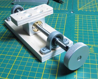
I used for construction some parts I bought in China (see parts list in pdf) and plywood in thickness 12 and 22 mm.
In the construction drawing you can see that I used parts A through F for this and the parts from the order list 1, 3, 4, 5, 6 and 8.
I use part 8 instead of the one that comes with the rod. because this one don't have backlash
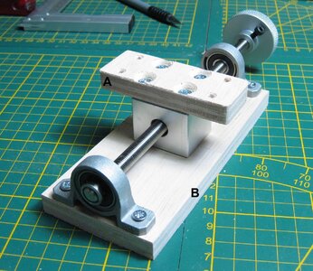
Part 5 I used to fix the bearing housing in B
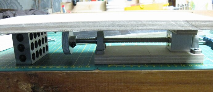
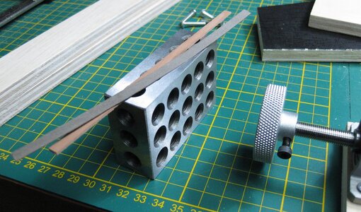
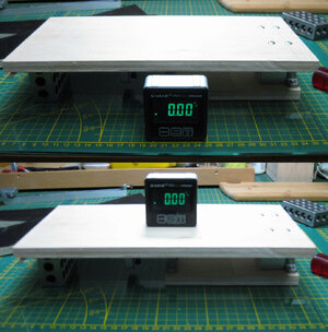
I used slats and a 123 block to ensure that part C runs parallel to B
Then I used super glue to put parts D against it. And afterwards secured it with screws. On the inside as support part E
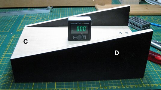
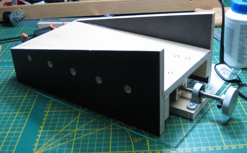
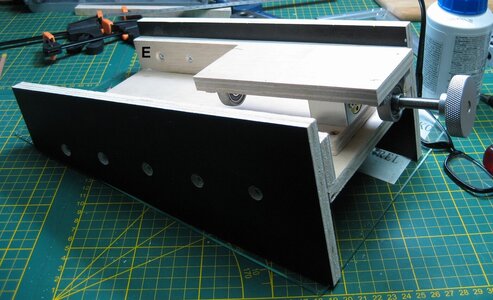
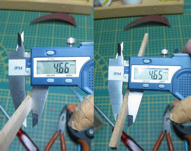
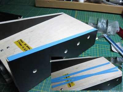
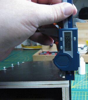
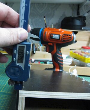
To fit the tabletop F, I use paper strips to adjust the tabletop. You see I use a glass to work on. This is more accurate when measuring things out.
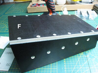
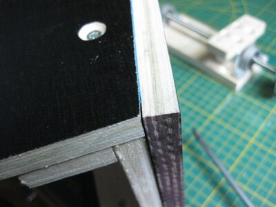
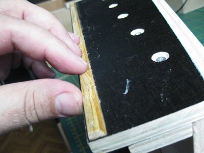
On the outside I attached a hardwood strip to make sure this will glide the table steady, when I adjust it.
Man, I wished I had a drum sander to make sure the hardwood strip is perfect in thickness. I did it with a piece of sandpaper and a lot of measurements to adjust it.
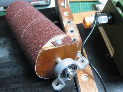
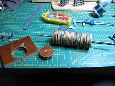
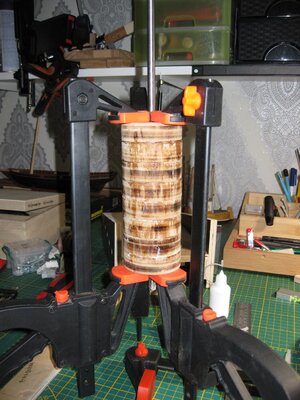
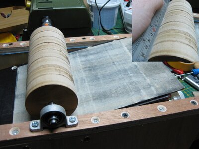
In between, I made the drum that the sandpaper will go around. This I made from 200 thick cherry wood that I have lying around. With the hole drill I made 60 mm. round discs and fixed them on the rod (part 7) with glue that connects wood and metal.
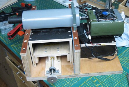
Then I started assembling the base where the adjustable table, drum and motor will be.
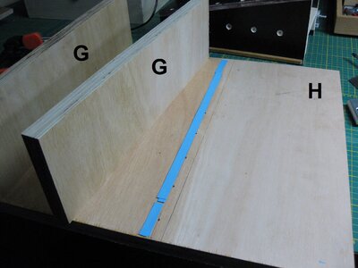
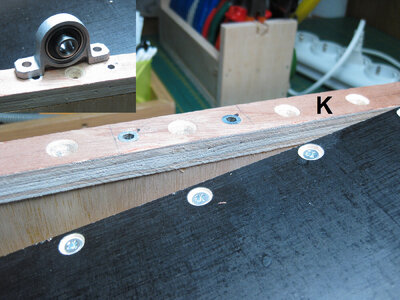
Again, used paper strips to get the parts G and H perpendicular to each other. Fastened everything from below with screws. And finally strip K mounted on top. The distance between the two plates G is determined by the width of the adjustable table.
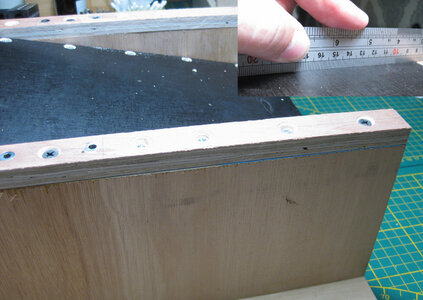
The drum on it after you have measured out where it should go. This is done by setting the table to its extreme position and then putting the drum on it, making sure that there is no space between the table and the drum. If you turn the table back the distance between drum and table will increase. This is quite a bit of measuring and precision. Make sure the axis is perpendicular to the walls.
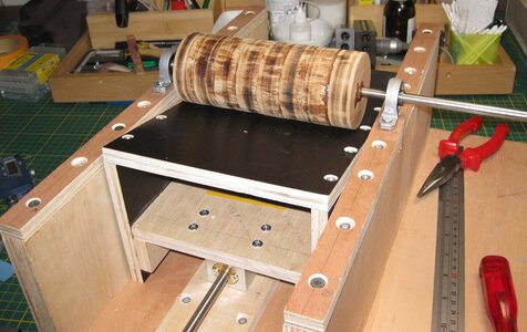
The motor can be adjust
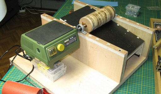
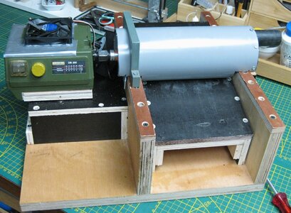
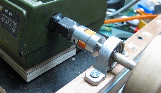
How you do this depends on what motor you use. If you use the same like I did you can put pieces of wood under the housing which can be screwed to the screwholes under the housing. Than make a table to fit the motor to. Just by measurement. In the last picture you can see how I did this, but there are many ways to do so. Make sure you put a coupler between the axe to make sure that every dis-alignment is capture by the coupler. It is listed in the parts list.
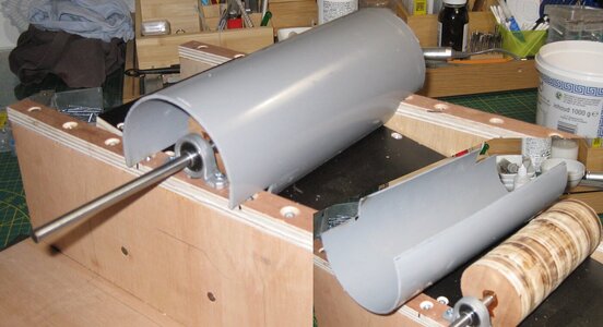
I made the dust cover from an old plastic pipe which I sawed in half and then fitted to the whole. At the end I put a vacuum cleaner nozzle which fits the vacuum cleaner. Make sure you can remove the hood.
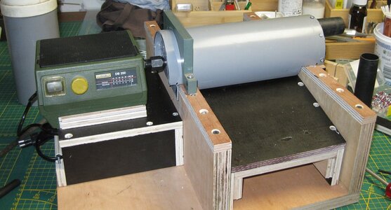
Now you can fit the drum and sand it smooth. I did this with a glass plate that I taped sandpaper to. By holding it under the spinning roller you make sure that the distance of the roller is the same in all places. The direction of rotation of the drum is always against the workpiece. Keep that in mind.
Max of pictures, I will go further in the next post.
First, I started with the sliding table and adjusting mechanism.

I used for construction some parts I bought in China (see parts list in pdf) and plywood in thickness 12 and 22 mm.
In the construction drawing you can see that I used parts A through F for this and the parts from the order list 1, 3, 4, 5, 6 and 8.
I use part 8 instead of the one that comes with the rod. because this one don't have backlash

Part 5 I used to fix the bearing housing in B


I used slats and a 123 block to ensure that part C runs parallel to B
Then I used super glue to put parts D against it. And afterwards secured it with screws. On the inside as support part E


To fit the tabletop F, I use paper strips to adjust the tabletop. You see I use a glass to work on. This is more accurate when measuring things out.


On the outside I attached a hardwood strip to make sure this will glide the table steady, when I adjust it.
Man, I wished I had a drum sander to make sure the hardwood strip is perfect in thickness. I did it with a piece of sandpaper and a lot of measurements to adjust it.

In between, I made the drum that the sandpaper will go around. This I made from 200 thick cherry wood that I have lying around. With the hole drill I made 60 mm. round discs and fixed them on the rod (part 7) with glue that connects wood and metal.


Then I started assembling the base where the adjustable table, drum and motor will be.
Again, used paper strips to get the parts G and H perpendicular to each other. Fastened everything from below with screws. And finally strip K mounted on top. The distance between the two plates G is determined by the width of the adjustable table.


The drum on it after you have measured out where it should go. This is done by setting the table to its extreme position and then putting the drum on it, making sure that there is no space between the table and the drum. If you turn the table back the distance between drum and table will increase. This is quite a bit of measuring and precision. Make sure the axis is perpendicular to the walls.

The motor can be adjust

How you do this depends on what motor you use. If you use the same like I did you can put pieces of wood under the housing which can be screwed to the screwholes under the housing. Than make a table to fit the motor to. Just by measurement. In the last picture you can see how I did this, but there are many ways to do so. Make sure you put a coupler between the axe to make sure that every dis-alignment is capture by the coupler. It is listed in the parts list.

I made the dust cover from an old plastic pipe which I sawed in half and then fitted to the whole. At the end I put a vacuum cleaner nozzle which fits the vacuum cleaner. Make sure you can remove the hood.


Now you can fit the drum and sand it smooth. I did this with a glass plate that I taped sandpaper to. By holding it under the spinning roller you make sure that the distance of the roller is the same in all places. The direction of rotation of the drum is always against the workpiece. Keep that in mind.

Max of pictures, I will go further in the next post.
Last edited:


