Explanation and Clarification of Scantling Lines

Joined
Jul 2, 2020
Messages
4,110
Points
588

Location
Eugene, Oregon
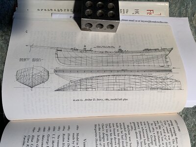
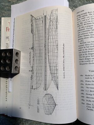
The attached photo is one example of a large number of schooners lines presented in The American Fishing Schooners by Howard Chapelle. These were taken off by him from old half hull models used for lofting and construction. I am puzzled by the lines curving back up toward the bar in the center as they are somehow related to the lines of the hull at the bottom of the set. WIthout stating my own assumption I would appreciate your explanation of those to me and how they differ from the hull lines below. Rich (PT-2)Scantling Lines.jpg
 
Hi Rich

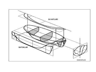
Actualy they are all hull lines

When you slice the hull like bread, you have the frames

When you slice it parallel to the sea level you have water lines

When you slice it parallel to keel you have buttock lines.

In short when you slice the hull in all three axis you obtain different lines.

It's a little bit confusing when they drawn on the same picture.

Best Regrads Bilal


Su Hatları = Water lines
Batoklar = Buttocks
En Kesitler = Frames (or cross sectons) :)

slide_3.jpg
 
Last edited:
Hi Rich

Actualy they are all hull lines

When you slice the hull like bread, you have the frames

When you slice it parallel to the sea level you have water lines

When you slice it parallel to keel you have buttock lines.

In short when you slice the hull in all three axis you obtain different lines.

It's a little bit confusing when they drawn on the same picture.

Best Regrads Bilal


Su Hatları = Water lines
Batoklar = Buttocks
En Kesitler = Frames (or cross sectons) :)

View attachment 222045T
Hi Rich

Actualy they are all hull lines

When you slice the hull like bread, you have the frames

When you slice it parallel to the sea level you have water lines

When you slice it parallel to keel you have buttock lines.

In short when you slice the hull in all three axis you obtain different lines.

It's a little bit confusing when they drawn on the same picture.

Best Regrads Bilal


Su Hatları = Water lines
Batoklar = Buttocks
En Kesitler = Frames (or cross sectons) :)

View attachment 222045
Thank you. I do understand some of those lines and "slices" but am confused about the few between the side elevation and those more closely packed set on the bottom half. . . What are the specific lines that curve way from the half model lines, back upwards to the lines shown on the "elevation" drawing lines?
Rich
 
Rich here is another example.

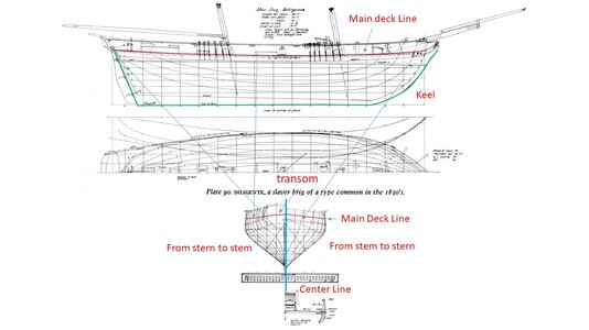
If you want to make a plank on bulkhead model, you must use center buttock line (which is keel) and half breadth lines (which are frames )

I draw green line to indicate the keel. On that part of drawing you can see vertical lines. These lines indicate the position of each frame.

After designating the keel. You must draw the frames from half breadth lines by mirroring each line from the center line which I draw with thick blue line.)

Half breadth lines are used on drawings to save space on the paper. One half is from stem to stern and the other half is from stern to stem.

I hope this drawing helps.

Bilal

Sunu1.jpg
 
Last edited:
Rich here is another example.

If you want to make a plank on bulkhead model, you must use center buttock line (which is keel) and half breadth lines (which are frames )

I draw green line to indicate the keel. On that part of drawing you can see vertical lines. These lines indicate the position of each frame.

After designating the keel. You must draw the frames from half breadth lines by mirroring each line from the center line which I draw with thick blue line.)

Half breadth lines are used on drawings to save space on the paper. One half is from stem to stern and the other half is from stern to stem.

I hope this drawing helps.

Bilal

View attachment 222085
Thank you for the additional drawing and annotations. On it I do see the lines that I was asking about with my photo but could not read. I went back to my jpg photo which I can enlarge and move around, which we cannot do with those shown in our postings, and saw the annotation for those lines as "Lines to inside of planking". I don't know how those were taken off unless the half hull model may have been of a "birds nest'" which was hollowed out the shell of the model would then be of the thickness of the ceiling planking inside and the frames. I have read of a few different types of half hull models in the book by Chapelle and will look those up. Rich
 
Great thread
For my POB Bluenose the primary set of lines provided and needed were those of the horizontal and vertical displacements for each bulkhead so that I could lay out my hull planking bands with correct spacing and widths. This thread helped in clarification of how I was reading the other lines and was totally not understanding the lines to the interior planks which would be needed for construction or a scratch build. I learn as I progress my voyage no matter the tack or gybing downwind. Rich (PT-2)
 
For my POB Bluenose the primary set of lines provided and needed were those of the horizontal and vertical displacements for each bulkhead so that I could lay out my hull planking bands with correct spacing and widths. This thread helped in clarification of how I was reading the other lines and was totally not understanding the lines to the interior planks which would be needed for construction or a scratch build. I learn as I progress my voyage no matter the tack or gybing downwind. Rich (PT-2)
I Googled around for "Birds nest half hull models" and see that they are a framed hull with only some hull planking. The spacing of the frames for those that I saw were consistent with Chapelle's comment that not all frames were included, say every third or fifth one depending upon model scale, and the shipwright had to work out the intraveining frames/fairing which explains why "sister ships" from the same model resulted in slightly different ships and sailing characteristics (sails and rigging aside). This was also clear in the scantling drawings in his book which show the locations of the stations and lines between those from which the hull lines are draws. If you Google these up you can see some of the models that may be for sale $$$. This has been an enlightening voyage for me. Rich (PT-2)
 
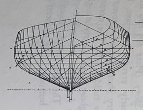
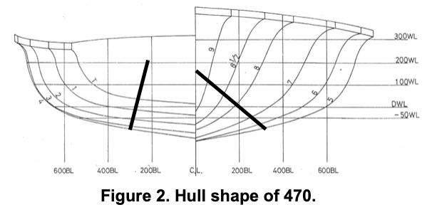
I believe the lines you refer to are the diagonals.
The three orthogonal sets (waterlines, sections and buttocks) are generally drawn first.
It is a long process to do by hand as you have to continuously measure from one to the other to get a consistant set of fair lines.
Diagonals are the measurements on the oblique lines in the section plan, and drawn outside of the general shape for clarity.
They help a lot to refine the fairing as they cross the frames at an angle close to 90° (it is difficult to accurately lift measurement of a point when the lines are at a very shallow angle).

Screenshot 2021-03-26 at 11.32.21.png
Where the frame shape is very different between the forward and the aft sections, the diagonals can be twisted at the midship to remain close to square angle. see second picture.
Screenshot 2021-03-26 at 11.55.58.png

The orthogonal form lines are used to create a table of offsets to loft the hull at the yard.
To the trained eye, a curve of areas and the diagonals give a much better impression of flow and behaviour than the form lines.
 
I believe the lines you refer to are the diagonals.
The three orthogonal sets (waterlines, sections and buttocks) are generally drawn first.
It is a long process to do by hand as you have to continuously measure from one to the other to get a consistant set of fair lines.
Diagonals are the measurements on the oblique lines in the section plan, and drawn outside of the general shape for clarity.
They help a lot to refine the fairing as they cross the frames at an angle close to 90° (it is difficult to accurately lift measurement of a point when the lines are at a very shallow angle).

View attachment 223317
Where the frame shape is very different between the forward and the aft sections, the diagonals can be twisted at the midship to remain close to square angle. see second picture.
View attachment 223318

The orthogonal form lines are used to create a table of offsets to loft the hull at the yard.
To the trained eye, a curve of areas and the diagonals give a much better impression of flow and behaviour than the form lines.
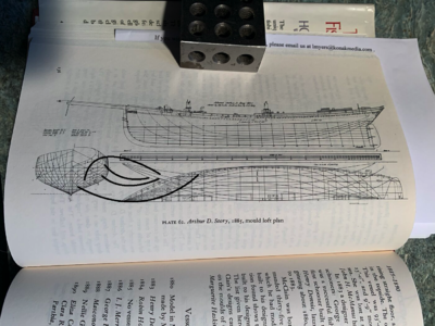
Thanks for this added information. On one of the pages showing the scantlings there was a small notation up with the lines that I am referring to seeing that said those lines were of the inside of planking. I'll attach/insert the jpg full size photo of that page and you can see the upwards curved lines trending back upwards to the scale in the middle.Scantling Lines.jpg
I don't know if you can read that or not without being able to zoom in very close.
I wonder if a "Hawks Nest" half mold model was used to obtain these lines drawn by the author?
Rich
 
The lines you refer to are indeed the diagonals.
see the picture.

The mention of "inside of planking" refers to the whole drawing.
Drawings are either used to be a representation of the finished hull, very useful for model makers.
However, the initial drawing is used to create a table of offsets, that will be later used to loft the frames etc... on the shop floor.
The shipwright would be annoyed if he had to subtract the planking on the loft, so a set of "moulded" lines is created.
(hint, the title "mould" loft plan)
Most yard half hull models (not the decorative ones) are also inside of planks.
The shipwright would take off offsets with callipers and scale them up on the floor.

The so called moulded dimensions (beam, depth etc...) are thus always inside of planking or plating, and outside of frames.
For the model maker, it creates an additional work to redraw the lines with the planks, then subtract the thickness of the model planks.
(or just subtract the difference)

Scantling Lines.png
 
Back
Top