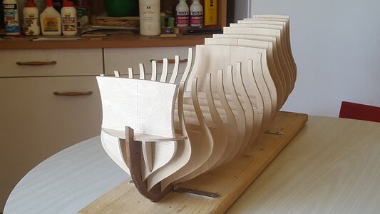
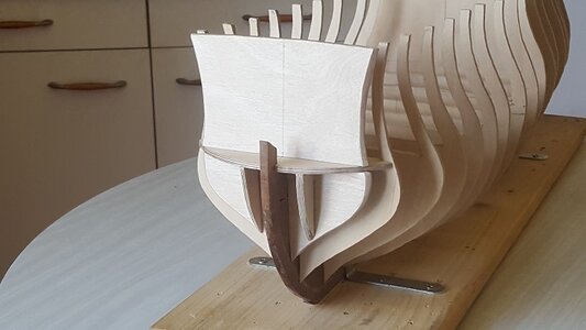
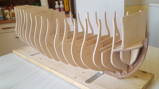
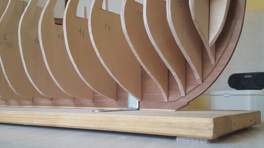
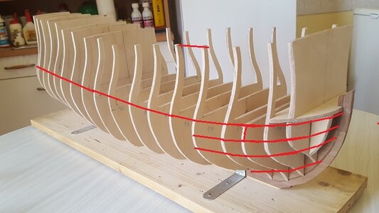
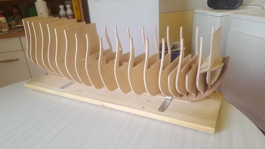
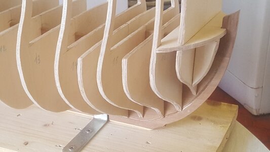
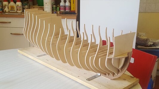
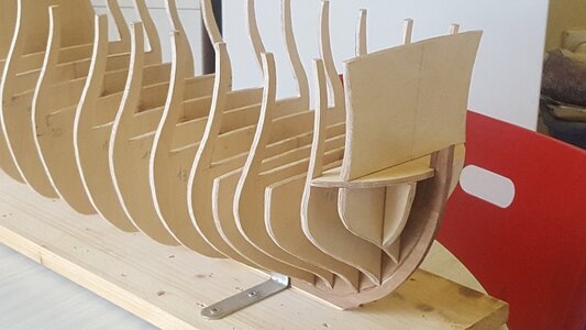
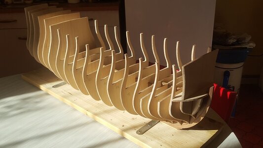
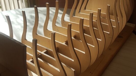
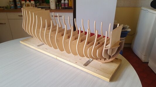
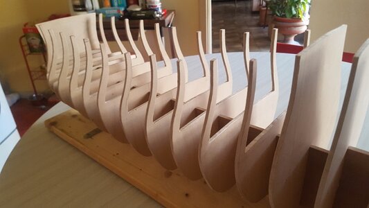
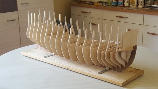
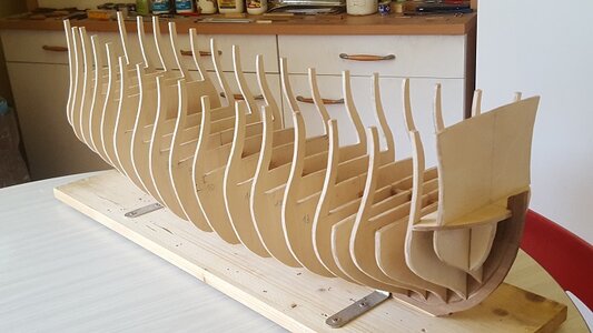
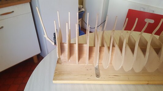
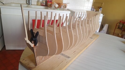
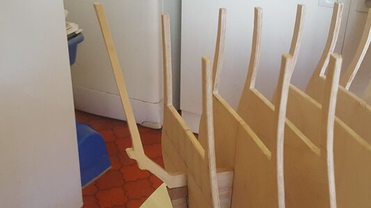
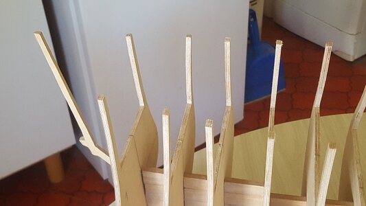
So we are looking forward to see the bulkheads finally fixed and shaped / bevelled ....
You are using an out of date browser. It may not display this or other websites correctly.
You should upgrade or use an alternative browser.
You should upgrade or use an alternative browser.
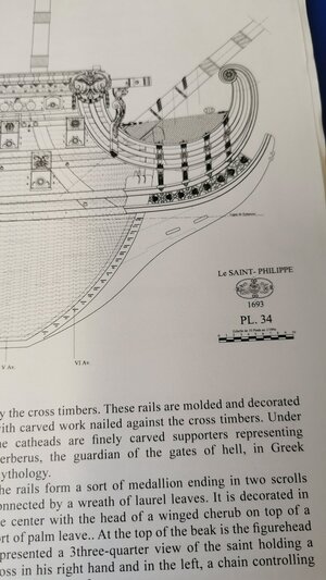
French war-ship Saint-Philippe 1693 - scale 1/72 - from Lemineur monograph
- Thread starter CRI-CRI
- Start date
- Watchers 62
-
- Tags
- saint philippe
This is going to be one beautiful ship!
Dear Christian,
thank you for also starting a SAINT PHILIPPE1693 - I do two projects on the same plans in 1/92 on a Heller's SOLEI ROYAL hull; and trying a hull model in 1/64 (for the ink copies I payed twice the price of the monography so you are the more smart guy awaiting a printed plan in 1/72) trying my self out on a recreation of her sister ship TONNANT 1693 bothz fighting as swimming battery in the Toulon siege varnishing the British artillery by their boardsides. And so my warm welcome in here...
As you may have figured out on yourself, there are some vital problems within the set of Plans I figured out - I bought the plans directly when published by preorder in the 1/48 first edition!These may be solveld in between - I do not know what is the status of the issues recently. I wrote a lot about these tasks in here:
https://shipsofscale.com/sosforums/...-in-1-64-pob-by-iterum.4465/page-6#post-98786
This may help a bit to you as the differences to 1/72 is overdone by using a factor of 88,8% ( https://finescale.com/~/media/import/files/pdf/9/c/0/tips_for_scales.pdf )
My main points of criticism are two:
The CWL
The CWL isn#t running throught the same measuring points on stem and stern - it is pivoted.
The Bulkheads
The Bulkheads are all in an 89,1° angle towards the keel
I stopped the project due to my unexpierncenet in wooden affairs.
Best wishes from Berlin,
Christian
Hi... Christian[...] I stopped the project due to my inexperience in wooden affairs [...]
My impression is that this model is unnecessarily complicated, one can perhaps arrive at the same result without
tilting the frames 1.2° out the vertical, and that to space them regularly doesn't change the general look of the hull
Best regards
Last edited:
That sounds interesting, Christian, as I am affraid about the exact location of the planking I wanted to pick up from the monography to construct the single shaped planks by this. So pivoting the bulkheads may shift all the planking's location.
I like your build very much and hope to see further progress.
What is your opinion to the pivoted CWL? I am still struggling with the drawingboards frostpaper and do think
about placing a new CWL right through the XVII foot marking at at the stem and stern post to press the water on the outside of the wale not having stayed it on the topside all the time with square formed big main scuppers dipping into the water...
I like your build very much and hope to see further progress.
What is your opinion to the pivoted CWL? I am still struggling with the drawingboards frostpaper and do think

about placing a new CWL right through the XVII foot marking at at the stem and stern post to press the water on the outside of the wale not having stayed it on the topside all the time with square formed big main scuppers dipping into the water...
Sorry, today, I've not found time to read the book joined ro the monograph
WL is always horizontal around the hull, I don't understand "pivoted CWL" expression (?)
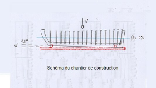
If you want to follow the 1.2° inclined frames, you have to slide a 1.2 cm hold under the front part of the
keel, to keep horizontal waterline (scale 1/72), the keel is tilted with the vertical frames, not the waterline :

Last edited:
Sorry, today, I've not found time to read the book joined ro the monograph
WL is always horizontal around the hull, I don't understand "pivoted CWL" expression (?)
If you want to follow the 1.2° inclined frames, you have to slide a 1.2 cm hold under the front part of the
keel, to keep horizontal waterline (scale 1/72), the keel is tilted with the vertical frames, not the waterline :
View attachment 224494
The keel certainly had had a fall there is no question about it. Here my scaled to 1/64 lines plan:
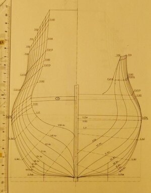
but the keel is shown in this lines plan horizontally and so the rule is the bulkheads had have to be rectangular to the keel, isn't it? so they cannot be rectangular to the CWL as she is bent in the Ar as in the Av section. So if she would be drawn as a horizontal line we would get presented a keel's underside view, wouldn't we?
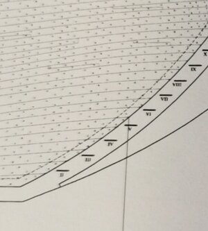
On the sideviewthe CWL isn't aline with the measurement Roman numbers at stern and stem. On the bow the line is above the XXVIII 's mark on stern below it.
And so the measurements are not correct or the CWL is pivoted. Both is possible so I have to figure out about it. So I will copy the stem's marks with lines on frost paper. By laying this it over the stern's markings it will appear if the distances are right or wrong. If they are right the CWL is pivoted down to the stern
So let's figure out.
Last edited:
Vertical projection of 1.2° inclined surface leads an image distortion
To correct it, the height parameter should be divided by 1/cos(1.2°) and this new height should be indicated to a drawing software in order to recalculate a new proportionnal projection
Then, the keel would appear inclined, and LF horizontal, as shown on my precedent post
As that angle is low, I took a fixed average value for LF height, without modifying proportions, which is an acceptable error at scale 1/72
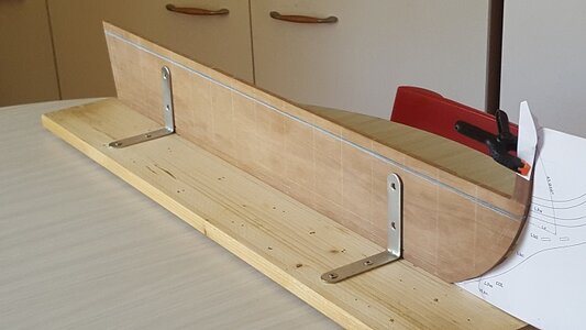
I redraw the keel for making it parallele (horizontal) with the median value of LF height and kept the frames as vertical
I can adjust as needed by carrying up the dimensions of the lateral views, but I think that it will not be necessary
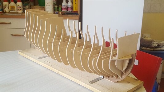


Last edited:
That sounds great and not too complex for me to deal with on a 21.2% bigger ship.
That vertical building board is a great idea.
Dear Christian,
that is really astonishing work you do. And her lines are so beautiful. Thanks a lot for motivating me in this manner.
Best wishes from Berlin, Christian Heinrich
that is really astonishing work you do. And her lines are so beautiful. Thanks a lot for motivating me in this manner.
Best wishes from Berlin, Christian Heinrich


