Great Lakes Steamship Benjamin Noble, 1:96 Scale Scratch Build

Joined
Jun 29, 2024
Messages
772
Points
298

This is a continuance of a Build Log currently “stranded” on MSW. My intent is to quickly review progress to date and to then proceed with the build as progress goes forward. Readers wishing a more detailed discussion of previous work will find it on MSW ( Scratch Built Models 1900 and later.

History

Lake Superior is by far the largest of North America’s Great Lakes, the five beautiful interconnected bodies of water that stretch through America’s Heartland. The four “upper” lakes; Erie, Huron, Michigan, and Superior, have long been used to transport vast cargos of steel making ingredients, iron ore, and limestone from mines in northern Minnesota and Michigan to steel mills in Chicago, Ohio, and Pittsburgh.

The lakes are freshwater that often freezes during the region’s bitter cold winters so throughout much of the Twentieth Century the shipping season began in late March and ended in December. Most of the time, the lakes do not have the large swells typical of the world’s oceans, but violent storms can occur particularly when the seasons change in the spring and fall. Also, unlike saltwater seas heavy coatings of ice can build up on topside surfaces. Relative to the oceans the lakes’ smaller size means that vessels can run out of “sea room” impaling thems on rocky shores.

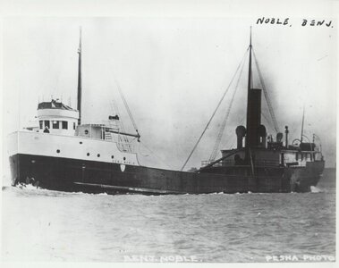
It was during such a storm that young Captain John Eisenhardt master of the 250ft long steamship Benjamin Noble found himself in the early hours of April 28, 1914 with a badly overloaded vessel. He had assumed command of the ship at Conneaut, Ohio on Lake Erie when her regular master, watching her being loaded with a heavy cargo of railroad rails consigned to Duluth, Minnesota at the extreme western end of Lake Superior, refused to take her out.

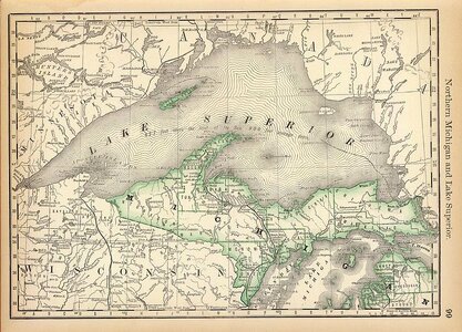
She almost made it, traveling across Lakes Erie and Huron, through the Soo Canal. On Lake Superior she emerged from behind the famous Apostle Islands into the funnel shape Western arm of the Lake. Having sailed this stretch of the lake, under normal conditions it is an easy trip; due west, deep water, and no navigational hazards. Unfortunately, however, only the very small port of Two Harbors offers any sort of refuge over this final stretch of lake and conditions were anything but normal. There is evidence that the Noble made it to Knife River only 20 miles from Duluth. By then, Captain Eisenhardt apparently found it necessary to seek shelter at Two Harbors Six Miles away but after turning back to the Northeast, the Benjamin Noble suddenly plunged to the bottom of the lake taking her entire 20+ crew with her. Despite efforts to find her and her crew, she was not discovered until 2005, 89 years later. The wreck divers who found her have filmed the wreckage and registered her on the National Register of Historic Places. They hope that the wreck’s deep location (300ft) will protect her from looters.
IMG_0626.jpegIMG_0625.jpeg
 
Last edited by a moderator:
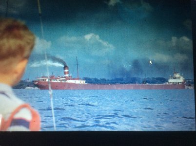
The Great Lakes are in my blood. When I was 3 years old, my father began construction of a 23’ L. Francis Herreshoff sloop that we later sailed on Lake Erie. I loved seeing the variety of big ships and loading and unloading equipment; Huelett unloaders and car dumpers that could turn a loaded rail car upside down into the hold of a ship. (First Photo.). Much later, I graduated from a University whose Alma Mater described itself as “goddess of the inland seas.” In the mid 1980’s I was living in Marietta, an Ohio River town, far from the Lakes but my parents were Living in Vermilion, Ohio on the South Shore of Lake Erie. The Inland Seas Museum, located in Vermilion had received a large collection of drawings from the American Shipbuilding Company, the principal shipbuilder on the Lakes. Christmas, 1986 my mother gave me a set of drawings for the Benjamin Noble that the museum had printed from the AmShip plans .

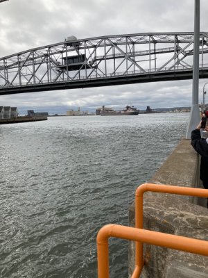
Three years later, the company that I worked for offered me the opportunity to move to Duluth, Minnesota to be involved in the management of a company that they had acquired. I didn’t need to think twice about accepting their offer. Now, I would be living 20 miles from where the Benjamin Noble sunk and being involved in the local boating and sailing scene would travel a couple hundred times through the Duluth Ship Canal that she was trying to reach. ( 2nd photo)

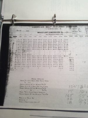
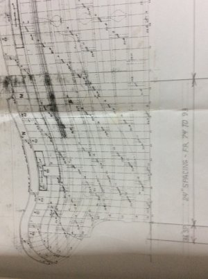
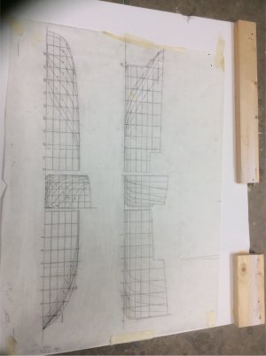
Upon opening the roll of 8 or so drawings I was disappointed to discover that they did not include a complete lines drawing. The one included was limited to the vessel’s graceful fantail stern. After moving to Duluth, however, a local museum director gave me a CD containing an index of all the available AmShip drawings . For the Benjamin Noble I found two items that I didn’t have; a Table of Offsets and a Plating Expansion Plan. (3rd and 4th photos). Using the table offsets, and the stern lines drawing, I could draw an accurate set of lines. (5th photo) I was now ready to build the model.

RogerIMG_0702.jpegIMG_0059.jpegIMG_0506.jpegIMG_0608.jpegIMG_0519.jpeg
 
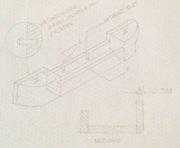
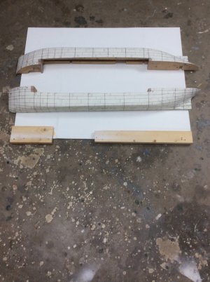
Ok, now time to make some sawdust! My preferred technique for building ship model hulls is the “solid hull” technique although in this case as we shall see, not really solid. My hulls are carved as port and starboard half models. Each half model can then be laid on a flat datum while carving and later marking our plating and other features of the hull. As shown in the sketch below, each half model includes three sections: the hull’s parallel mid body, made from three pieces to form U cross section, and solid bow and stern sections fit and glued into each end of the mid section. Wood is ordinarily 1” nominal thickness lumberyard pine.

Before shaping the hull, holes for brass locator pins are drilled at two locations into each of the hull halves these are best drilled with the drill press and the block laying on a flat surface. With the block again laying flat, the bandsaw was then used to cut the profile including the sheer. The bilge radii were shaped using the correct sized router bit.

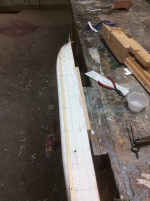
The hull was then carved to shape. My favorite carving tools for this are three very small bronze spokeshaves bought in 1965 when I was a member of a student team carving a model of a tanker to be towed in the University of Michigan’s 400ft long towing tank. Cardboard templates copied from the lines drawing body plan were used to check progress. Photo of the carved hull halves painted with white epoxy paint below.

Roger

IMG_0551.jpegIMG_1169.jpeg
 
The next step was to add the shell plating on the hull. Most of the Noble’s hull was plated using the “in and out” out method where the IN strake fayed directly against the framing and the OUT against its two IN neighbors. The plating is shown in detail on the plating expansion drawing, partly shown above. By 1909 the in and out method had largely replaced the earlier clinker method that required expensive tapered steel backing strips between the plating and frame.

My original intent was to plate the hull with .005” sheet brass secured with 3M transfer tape. To apply, transfer tape is applied to one of the two surfaces. The paper backing is then removed leaving a thin coating of adhesive. Long story short, it didn’t work. The edges of the brass plating lifted, and frustrated, the model was put on the shelf while I built another model.

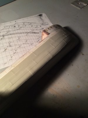
In early 2020 I decided to again tackle the plating problem. I found a supply of high quality paper in a drawer, sprayed it with shellac and glued it to the hull with PVA glue. Almost 5 years later it shows no sign of failure. But first, I had to Mark Out the plating on the hull with the plating pattern. First was to cut a number of paper tick strips. These were each laid against the plating expansion and the plating strakes marked. Next the strakes were marked on the hull from the tick strips. I have some Sitka Spruce from a long ago Old Town Canoe rebuilding project that I ripped into battens. These battens were then tacked to the hull at each tick mark. A little juggling was sometimes required for a fair curve.

Determining the plating arrangement on a ship’s hull was an art. The key was to use wherever possible full plates. In Noble’s case, 8ft wide x 24 ft long. Cutting and shaping plates was expensive and wasted material. After plating the model, I was surprised to find that very few, required special shaping.

IMG_0659.jpegIMG_1279.jpeg
 
A very interesting build.

I grew up in South Western Ontario near the south end of Huron and the St Clair river and always enjoyed watching the lakers come and go. My favourites are still the older designs like the Alpena and Ojibway ( struck off in 2022 ).

I will follow along to see where your Benjiman Noble goes.

cheers, Graham
 
Nice to see here the progress of your build, Roger. And also that you are building your model in 2 halfs, using the old line drawing and plating-plan. Pretty much the same base and principles as I used for my current Balder model, but with a different approach.
So, I sat my chair and will follow it with great interest.

PS: Although your model is not ‘saw’ in 2 halves, but I think it falls under Half-Cut, I will ask the other members Uwe @Uwek and Maarten @Maarten if they have any objection to offering you the membership of the HCSA (Half-Cut Saw Association).:)
Regards, Peter
 
Last edited:
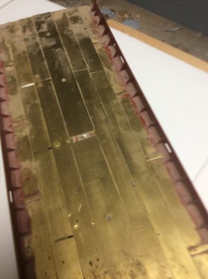
My approach is to build this model in modules before final assembly. The next major module is the main deck assembly. Great Lakes vessels in the traditional bulk cargo trades do not have bulwarks. When loaded they have relatively low freeboard so anything that traps water on decks is to be avoided.

Benjamin Noble did have bulwarks as she was designed to haul pulpwood. Pulpwood is a light cargo that would fill the hold without loading the ship to its design load waterline. These vessels, therefore, routinely carried a large deck load. The bulwarks plus the raised forecastle and poop deck formed a box to contain the deck load. As we shall see, this box prove could to be quite dangerous under some loading conditions.

IMHO the best material to simulate metal is metal; in this case brass due to its ease of fabrication. Sheet brass can be cut distortion free with a guillotine paper cutter and heavier material is easily cut with my Byrnes saw. It is joined with ordinary soft solder. The brackets were an interesting exercise in sheet metal folding. They were then put under the mill to trim the flanged edges uniformly.

Main deck assembly. The main deck is pierced with six hatches. These hatches will cover gaps in and nails securing deck plating:

IMG_0557.jpeg
 
Last edited:
Very cool build. I never thought of carving a ship hull to shape from a block of wood. I had a question about your process. Does applying shellac to paper alter its texture or increase its rigidity? I'm asking, because I have to start thinking about creating "iron plates" to my own build and am currently trying to find alternatives to using blackened brass.
 
Both. Shellac increases its rigidity and makes it more durable. It can even be lightly sanded.

The carved hull is an old fashioned way to fashion model ship hulls. It was used extensively prior to the introduction of European Plank on Bulkhead kits in the 1970’s and was used by professional model builders for experimental models built to be towed in tanks to determine hull resistance. It is still the preferred method for high quality exhibition models.

Roger
 
Back
Top