Gunboat Caustic from dlumberyard

Joined
Jan 8, 2021
Messages
213
Points
143

Hello
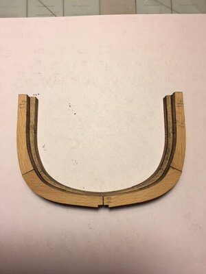
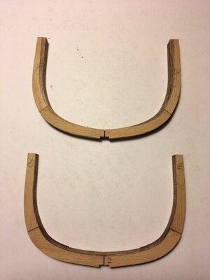
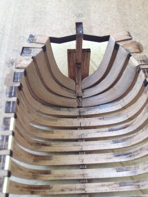
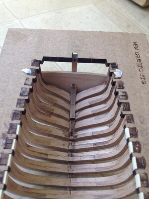
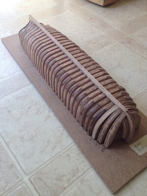
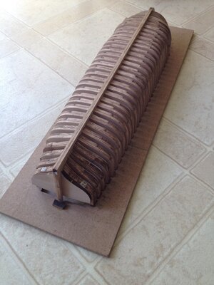
This will be my build log on the Caustic Ive been familiarizing myself with the various parts of the kit and spending time looking at how frame pieces are setup on new concept of using a jig. I’m also watching the videos presented by Dave Stevens as a guide.
As I progress I will add photos.

P1 Box contents.jpegP2 First frame.JPG
 
I'm approaching completion of building frames 1 through 25. I'm looking at drawing in bevel line on inside of frames and ask if my assumption is correct.

As a test to draw inside bevel on frame 1 I set frame 2 on top , aligned both and then drew pencil line on frame one with two as guide. I then shaded in area on frame one. I've attached photos. Your thoughts please. Thanks
 

Attachments

  • P4 Establishing bevel line Fr 1.JPG
    P4 Establishing bevel line Fr 1.JPG
    32.3 KB · Views: 13
  • P5 penciled in fr 1 bevel.JPG
    P5 penciled in fr 1 bevel.JPG
    33.5 KB · Views: 11
Spent today checking fit of each full frame in keel. Decided for fun to dry fit all of them and take photo.

Will be doing some more cleanup of char then adding bevel line on inside.

P7 Temp frame setup in keel.JPG
 
Last edited by a moderator:
I'm approaching completion of building frames 1 through 25. I'm looking at drawing in bevel line on inside of frames and ask if my assumption is correct.

As a test to draw inside bevel on frame 1 I set frame 2 on top , aligned both and then drew pencil line on frame one with two as guide. I then shaded in area on frame one. I've attached photos. Your thoughts please. Thanks
As a follow up to this post and a caution . The above attempt to create a line for fairing frame by laying one frame on top of another is incorrect. See example A.

When frame 2 is located in its proper spacing on keel the angle changes . See example B.

Thanks to Dave Stevens for his extended explanation to my question.
 

Attachments

  • A.JPG
    A.JPG
    69.4 KB · Views: 9
  • B.JPG
    B.JPG
    73.4 KB · Views: 9
Built keel assembly yesterday. I just did a bit of sanding and she fits in jig. Slipped frames 1, 11,17 and 25 to see how they line up. Purchased epoxy and once everything is aligned I'll start gluing them in place.

P8  Beginning frames in jig.JPG
 
Last edited by a moderator:
Built keel assembly yesterday. I just did a bit of sanding and she fits in jig. Slipped frames 1, 11,17 and 25 to see how they line up. Purchased epoxy and once everything is aligned I'll start gluing them in place.

View attachment 231213
step by step - a shipüs hull is growing - this is for me every time one highlight in between, when the framing is permanently in place and you have a "Ship in hand" :cool:
 
Currently cutting bow timbers to fit. Then bevel inside of cants and glue them in place . Dave provided two pieces of wood that will need to be shaped to suit space between cant and bow timber. After that I'll move on to stern frames.

The work on getting can't frames to lay flat against the deadwood was a good challenge .

I hope this post finds everyone well .

P10 Bow frames.jpg
 
Last edited by a moderator:
Finished attaching last cant frame today. In lieu of finishing bow with bow blocks I continued with stern cants .
So, hull work needed are blocks, sanding hull inside and out and then the attachment of the keelson. You might notice that I did some beveling of the cant frames
prior to installation. Thought this would help with sanding task.
Once done I can start working on inside, clamps, beams etc.
 

Attachments

  • P11a Cants.jpeg
    P11a Cants.jpeg
    90.1 KB · Views: 18
  • P11b Cants.jpeg
    P11b Cants.jpeg
    97.3 KB · Views: 16
  • P11c Cants.jpeg
    P11c Cants.jpeg
    92.2 KB · Views: 16
  • P11d Cants.jpeg
    P11d Cants.jpeg
    84.1 KB · Views: 15
I shifted from my Oneida build to do some sanding of inside hull on the Caustic. Ive also been mulling over how to fill gap between last cant frame and bow timber.
First , the sanding task. I’m using 40 grit sandpaper affixed to both sanding sled and sanding sticks. It does a nice job of taking off wood. I’m getting close on port side cants for run of clamp on that side.
I have a template I set against the frames to see how I’m doing.
As for the how to handle the gap mentioned above , Dave provided blocks of wood for this task.
His helpful videos show use of machine to assist with sanding the initial shape to fit. I’m doing it a bit differently , as I don’t have a machine of that level. I have enough extra wood on the laser sheet to cut
pieces that can be shaped and glued together building from the bow timber to the cant frame.

I hope you are all enjoying your time on each of your builds.

Take care
 
Ive been working on bow cant frames to lower the foot to meet the bow timber. The attached drawing show how I believe they should rise up and meet the timber.
I also started experimenting with sanding disk at outside of hull at bow. Using Dave Stevens suggestion to size the disk to cover at least 3 frames I tried my hand
and feel that it will do the job. So, thanks Dave.
 

Attachments

  • IMG_1026.jpg
    IMG_1026.jpg
    249.5 KB · Views: 9
  • IMG_1027.jpg
    IMG_1027.jpg
    141.1 KB · Views: 8
  • IMG_1028.JPG
    IMG_1028.JPG
    254.2 KB · Views: 8
  • IMG_1030.jpg
    IMG_1030.jpg
    95.7 KB · Views: 7
This is looking good, soon the whole hull will be done and ready for next stage of the build.

Keep up the great work and photos.

Kurt
 
This is looking good, soon the whole hull will be done and ready for next stage of the build.

Keep up the great work and photos.

Kurt
Hello Kurt
Thank you for your encouragement and soon on to the next stage.
 
While I finish with sanding, I took wood for clamps and after boiling and using guide of inside curve, set them up to dry.

Watching Daves video on attaching clamp I need to invest in various spring and "C" clamps to hold wood clamp to frames.
 

Attachments

  • Clamps drying.jpg
    Clamps drying.jpg
    266.4 KB · Views: 9
Back
Top