HMS ALERT 1777 cutter POF by shota70 [COMPLETED BUILD]

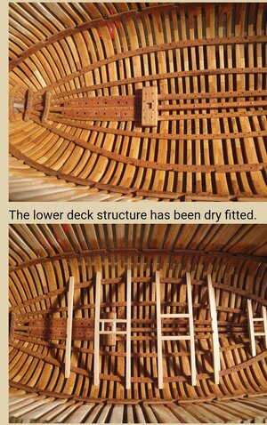
After studying the photos and drawings you sent me (in the last few days), the construction logs and other information available to me I came to the conclusion that timber number EL 82 connects to parts DL54 and Frames number 9 in the jig. Attaches a picture of the parts laid out, not glued.
View attachment 304284
It's a bit funny to ask a question out loud to everyone and not wait for an answer :D, but find it ourselves.
I will try to keep the documentation detailed for the next members who will reach these stages in a few weeks or months.
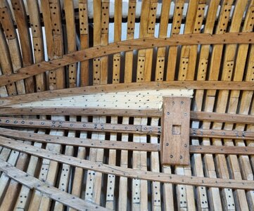
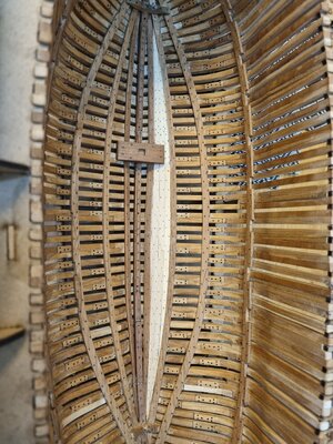
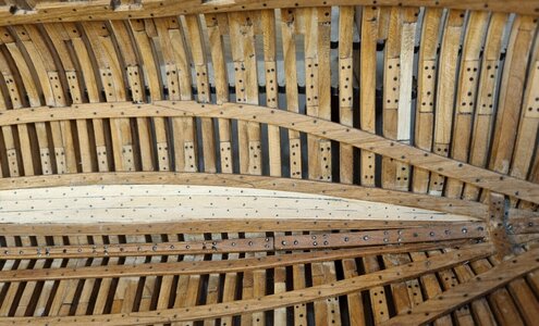
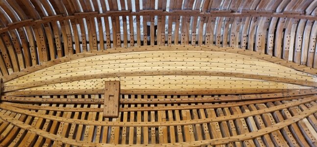
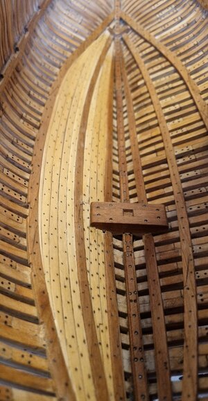
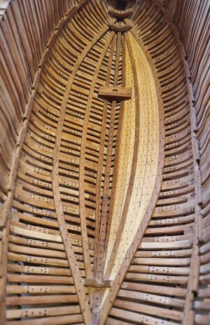
Once the question of the location of the beams has been resolved for the time being, I will move to the installation of planking in the inner and lower part of the deck similar to the beautiful work that our friend Maarten did - I will attach a picture of his work
View attachment 304285
Often I try it in the way you made it already - cutting out the parts, and check at the location if the part there is making sense..... and it is making sense
and there is the notch for the hanging knee and also for the carling - so it is fitting
At the end it was only a small typewriting error
 
Good evening friends
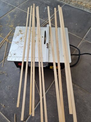
Today I started preparing the planking of the inner / lower deck.
I started by cutting the wooden boards to a width of 3.75 ml.
20220422_140453.jpg
I measurement the required lengths and marking them with wax paper
20220422_161548.jpg20220422_174038.jpg
and glued after I made the dots that simulate the round wooden pegs.
Attaches photos of the work and the intermediate result.
20220422_181602.jpg20220422_181613.jpg
 
Beautiful!
Your planking is looking superb my friend.
Often I try it in the way you made it already - cutting out the parts, and check at the location if the part there is making sense..... and it is making sense
and there is the notch for the hanging knee and also for the carling - so it is fitting
At the end it was only a small typewriting error
thank you very much my dear friends For your support and compliments
 
Here the same like I do with other build. I only hit the like button, but it means you do a fantastic job and I enjoy your build. Thanks for sharing it with us.
 
You are making great progress Shota.
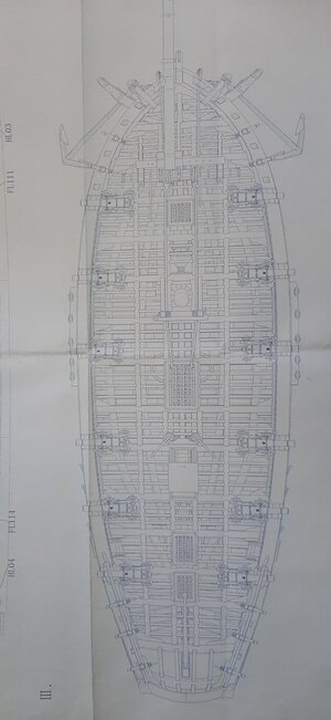
If you are missing the blue print deck drawing I can scan it for you and PM it tomorrow.

Regarding the EL and DL you are right, there is a mistake here in the manual.
 
You are making great progress Shota.
If you are missing the blue print deck drawing I can scan it for you and PM it tomorrow.

Regarding the EL and DL you are right, there is a mistake here in the manual.
thanks my dear friend :D
I will be happy if you could scan the blue print deck drawing for me
 
Hello friends
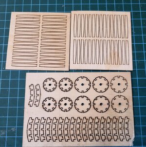
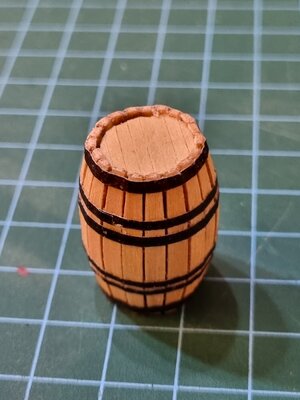
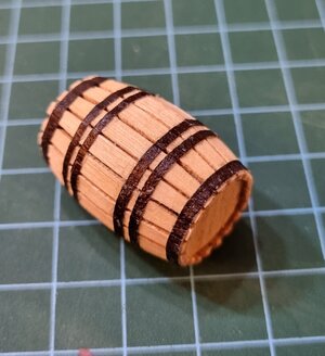
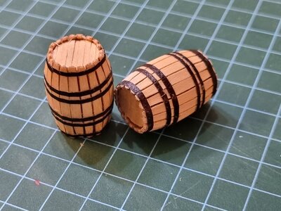
After several days of Break from the construction process on the ship, I devoted the evening to creating the water barrels that Trident Model provided in the kit.
After reviewing the building instructions booklet as well as the construction logs I noticed a lack of documentation of how the barrels are built in detail for the benefit of those who are less proficient / like me.
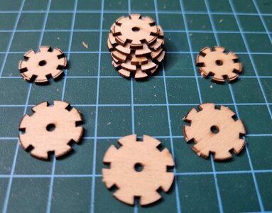
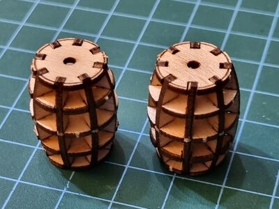
Therefore, I will detail a little in the description and photos that I will attach. First I took out the ten round discs. Each bundle consists of five discs, 2 small, 2 medium and one large in the middle.
20220427_192038.jpg20220427_194412.jpg
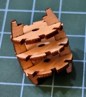
I connected the discs with the long pillars built like zipper teeth. I reinforced the structure created with wood glue.
20220427_195251.jpg20220427_195501.jpg20220427_195902.jpg20220427_201927.jpg
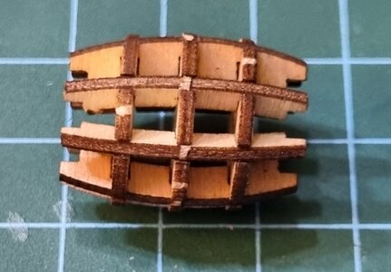
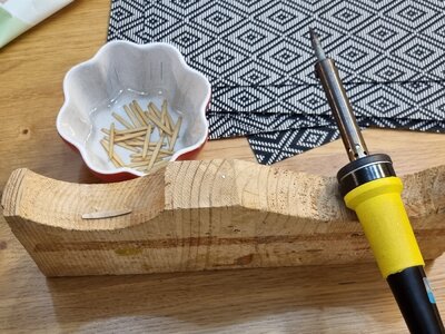
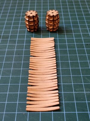
I continued to remove the wooden beams that were supposed to wrap the structure of the barrel , I soaked them in hot water for about 20 minutes and after feeling the wood soften, I shaped the concave shape using solder in a lump of leather wood.
20220427_211520.jpg20220427_214640.jpg
Tomorrow or the day after tomorrow I will stick them to the barrel chassis and make the metal hoops of the barrel as well as seal the lid and bottom of the barrels with matching wooden boards. Good night
 
You are making great progress Shota.
If you are missing the blue print deck drawing I can scan it for you and PM it tomorrow.

Regarding the EL and DL you are right, there is a mistake here in the manual.
Hi Shota,

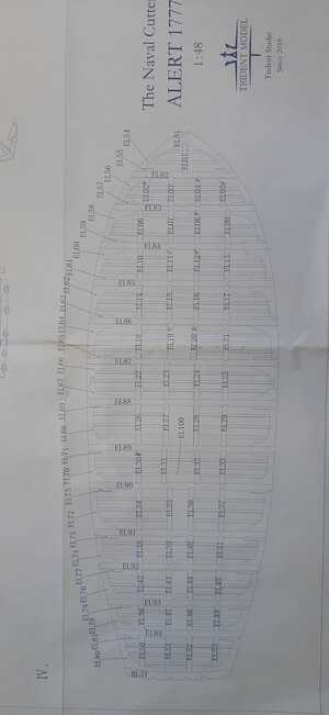
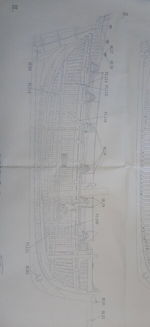
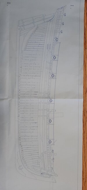
Drawing is unfortunately too big for my scanner. See below pictures I took per part of the drawing. Hope these are better then the ones you already received.

20220428_111324.jpg

20220428_111303.jpg

20220428_111242.jpg

20220428_111221.jpg
 
hello dear friends
Tonight I continued to create the barrels of the ship.
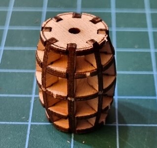
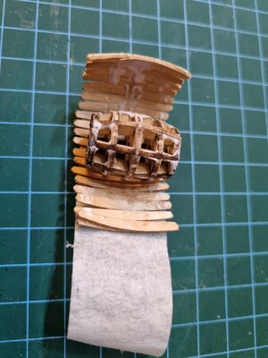
I started by gluing the shell beams of the barrel to duct tape, next to each other. After that I applied wood glue to the barrel chassis and attached the beams to the chassis so that the paper glue produces an external gravel that attaches the beams to the chassis.
On a layer of paper glue, I stretch the rubber bands to fasten the beams to the chassis.
Unlike some of the members I decided to replace the metal rims with relatively thick adhesive paper painted black.
I believe it gives an accurate and proportional effect to the thickness of the hoop in the original barrel.
I also used wood glue to glue the hoops.
after that I created the lid and bottom of the barrels. I used the duct tape, which I drew two circles of the required size and on which I glued narrow, thin wooden beams, in order to maintain the correct scale and proportions.
Unfortunately tonight because I was so focused on creating the barrels, I forgot to film the process in detail.
20220428_203042.jpg20220428_215716.jpg20220428_215647.jpg20220428_224614.jpg20220428_224757.jpg
good evening friends
 
Wow. The barrels came out beautifully my friend - they look very authentic!
 
hello dear friends
Tonight I continued to create the barrels of the ship.
I started by gluing the shell beams of the barrel to duct tape, next to each other. After that I applied wood glue to the barrel chassis and attached the beams to the chassis so that the paper glue produces an external gravel that attaches the beams to the chassis.
On a layer of paper glue, I stretch the rubber bands to fasten the beams to the chassis.
Unlike some of the members I decided to replace the metal rims with relatively thick adhesive paper painted black.
I believe it gives an accurate and proportional effect to the thickness of the hoop in the original barrel.
I also used wood glue to glue the hoops.
after that I created the lid and bottom of the barrels. I used the duct tape, which I drew two circles of the required size and on which I glued narrow, thin wooden beams, in order to maintain the correct scale and proportions.
Unfortunately tonight because I was so focused on creating the barrels, I forgot to film the process in detail.
View attachment 305846View attachment 305847View attachment 305848View attachment 305849View attachment 305851
good evening friends
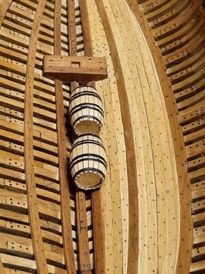
I am assuming that the coincidence between your superb barrels and Heinrich's post @Heinrich , Post in thread 'HIGH HOPES, WILD MEN AND THE DEVIL’S JAW - Willem Barentsz Kolderstok 1:50' https://shipsofscale.com/sosforums/threads/high-hopes-wild-men-and-the-devil%E2%80%99s-jaw-willem-barentsz-kolderstok-1-50.8662/post-238817, is purely accidental, but I do have my doubts
 
Hello dear friends
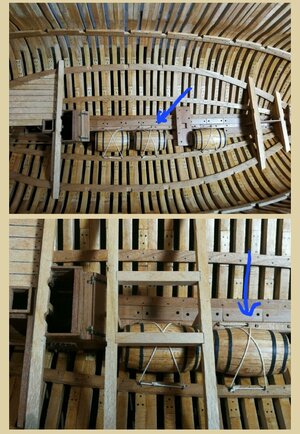
I'm asking for your help in guiding and explaining, in some of your models (PeterM) Screenshot_20220430-164437_Chrome.jpg
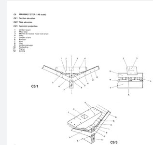
as well as in the pictures that the creator of the model attached, appear next to the keelson Limber board boards. Screenshot_20220430-162432_Chrome.jpgScreenshot_20220430-164053_Drive.jpg
The questions are:
What is the purpose, what they used for? From what point does the laying of these boards begin and where does it end?
I saw that some of you put them only on one side of the keelson and not along it, I would love for her to know why ?
Thank you very much
 
Hallo Shota, I believe that the limber passage was used to collect the water and lead it to the pumps. The limber boards cover the passage, so that the sailors don't get wet feet. You can cover the limber passage all the way along the keel or just parts of it, as You like.
 
Back
Top