
Great progress and work - Bravo

You are using an out of date browser. It may not display this or other websites correctly.
You should upgrade or use an alternative browser.
You should upgrade or use an alternative browser.
HMS Bellona 1760 1:75 Timber [COMPLETED BUILD]
- Thread starter Navis Factorem
- Start date
- Watchers 15
-
- Tags
- bellona completed build

Hello David, just catching up on your build log, and its really looking very impressive. ")
- Joined
- Jan 15, 2021
- Messages
- 40
- Points
- 93

More rainy weather, more days indoors ship building.
The upper deck is now complete, more guns more gun tackle. I assembled all the tackle before installing the guns. Having done the tackle with the guns in place on a previous project (with far fewer guns!) I decided there had to be a better way so a bit of artistic license resulted in some of the tackle being represented by thin timber strips where it is tucked away below decks or gangways but where more visible, such as the the train tackle, I have made up blocks from 2x2 mm walnut and ring bolts from 0.5mm brass wire finished with chemical blackening.
More work has been done on the detail hull decoration. Again a bit of artistic license has been applied and an "impressionist" approach has resulted in details which are pretty rough when viewed up close but I think create a reasonable look when seen in the overall.
- Joined
- Jan 15, 2021
- Messages
- 40
- Points
- 93
Hi, My Bellona build is progressing to the point where I am assembling deck fittings related to the rig.
The standing rig looks relatively straightforward despite the massive number of shrouds and chains.
The running rig presents some difficulties.
I was able to substantially complete the running rig for my previous build, HMS Surprise, as I have Lennarth Petersson's excellent book "RIGGING PERIOD SHIP MODELS" which is based on a ship quite similar to Surprise. So rope layout and most importantly the belaying patterns at deck level was well described.
The running rig for Bellona is basically a scaled up version of Surprise but the similarity ends when the ropes hit deck level. Surprise has extensive belaying pin racks attached to the bulwarks, Bellona does not, so where these ropes terminate is a bit of a mystery. At the forecastle the bowsprit and foremast lines seem to terminate at the many timberheads that surround it. Others terminate at the forecastle rail. I am unable to work out which lines terminate where. The desination at deck level of the main and mizzen ropes is a complete mystery to me.
Any advice that the SOS collective mind can provide would be greatly appreciated.
Thanks and cheers, David.
I do not have the details of the Anatomy book about the Bellona in mind, but did Lavery not explain the belaying points detailed enough?
Based on the first post of this topic we know, that you have the book by hand....
Based on the first post of this topic we know, that you have the book by hand....
Book review - The 74-Gun Ship BELLONA" (Anatomy of the Ship) by Brian Lavery
Book Review: The 74-Gun Ship BELLONA - (Anatomy of the Ship) by Brian Lavery My copy is the original version published by Conway Maritime Press in 1985, the revised version has an additional 1:96 scale fould out plan in the book cover Hardcover: 120 pages Publisher: Conway Maritime...
shipsofscale.com
- Joined
- Jan 15, 2021
- Messages
- 40
- Points
- 93
The Lavery Anatomy book includes quite a detailed layout of the running rig at the spars and masts and has lots of arrows on lines pointing towards the deck but does not have what happens when they reach deck level. I can make an educated guess as to which ropes run through sheave blocks and terminate at the pin racks at the base of the masts but this only covers the heavier ropes.I do not have the details of the Anatomy book about the Bellona in mind, but did Lavery not explain the belaying points detailed enough?
Based on the first post of this topic we know, that you have the book by hand....
Book review - The 74-Gun Ship BELLONA" (Anatomy of the Ship) by Brian Lavery
Book Review: The 74-Gun Ship BELLONA - (Anatomy of the Ship) by Brian Lavery My copy is the original version published by Conway Maritime Press in 1985, the revised version has an additional 1:96 scale fould out plan in the book cover Hardcover: 120 pages Publisher: Conway Maritime...shipsofscale.com
I know that kits of 74s exist. Could possibly the kit instructions that include a belaying plan be scanned or photographed and included in a message.
Again, any information that can be provided would be greatly appreciated.
Cheers, David.
- Joined
- Jan 21, 2022
- Messages
- 534
- Points
- 353

I've sent you pm.
Maybe some lines end at shroud cleats.La Bretagne french vessel has such endings. At the same time there's other very similiar ship L'Ocean which has pin rack
 www.modelships.de

Maybe some lines end at shroud cleats.La Bretagne french vessel has such endings. At the same time there's other very similiar ship L'Ocean which has pin rack
Photos model of the 100 gun ship La Bretagne of 1766
www.modelships.de
- Joined
- Jan 15, 2021
- Messages
- 40
- Points
- 93
Thanks for the replies.
I am gradually getting an idea of where various ropes terminate at deck level.
Possible pin racks towards the bow end of the quarterdeck could be a bit of a problem due to gun locations and the height of the bulwarks. The termination of many of these ropes on shroud cleats as shown on the great photos of the model solve this and this is probably what I will do.
Cheers, David
- Joined
- Jan 15, 2021
- Messages
- 40
- Points
- 93
Update time.
All decks are now permanently fixed in place and the deck fittings are progressing. The bellfry was a good little challenge. The long guns on the forecastle and the carronades on the poop deck will be installed once the shrouds are in place so there is no positions clash. Setting out the gun ports on the lower decks had to be carefully considered with the lower sections of the masts in place and dummy shrouds run.
The rudder has been fabricated and installed along with more of the stern detailing.
The poop deck skylight was again glazed using the PVA method.
Picking up the hull and turning it to work on opposite sides was becoming a real problem so an essential addition to equipment is a "lazy susan" style stand with a swivel fitting from the local hardware store. The plywood base can be chocked and the turntable locked to enable work on hard to reach bits on the hull.
It's almost time to start on masting and spars.
Cheers, David.
- Joined
- Jan 15, 2021
- Messages
- 40
- Points
- 93
I have reached a milestone. The mast components have been made and for the first time I can see the full size of the model. It's pretty big at about 1,050mm long and about 900mm high. When the yards are fitted, the widest being the main yard the model will be about 400mm wide. That's going to be one BIG perpex box!

- Joined
- Jan 15, 2021
- Messages
- 40
- Points
- 93
Update time for my Bellona build.
Work on the hull is nearing completion and the start of the rig is getting closer.
The chains have been made using 20 gauge brass wire and the deadeyes fitted. The chain sections are shaped using a block of hardwood as a mandrel with pieces of wire of different thickness and at different spacings to make the shapes. Once made up the chains are then disassembled and treated with a chemical blacking agent. Then reassembled.
I believe that getting the chain angles right is really important so I spend quite a lot of time with the masts in place and dummy shrouds to mark out the angles. there is also quite a bit of pre-planning needed to ensure that there is no conflict with the shrouds and the gun port positions so very early on in the hull construction I marked out the chain positions.


Cheers, David.
Work on the hull is nearing completion and the start of the rig is getting closer.
The chains have been made using 20 gauge brass wire and the deadeyes fitted. The chain sections are shaped using a block of hardwood as a mandrel with pieces of wire of different thickness and at different spacings to make the shapes. Once made up the chains are then disassembled and treated with a chemical blacking agent. Then reassembled.
I believe that getting the chain angles right is really important so I spend quite a lot of time with the masts in place and dummy shrouds to mark out the angles. there is also quite a bit of pre-planning needed to ensure that there is no conflict with the shrouds and the gun port positions so very early on in the hull construction I marked out the chain positions.
Cheers, David.
Very good result
How did you make the blackaning of the brass material after the installation on the hull?
How did you make the blackaning of the brass material after the installation on the hull?
- Joined
- Jan 15, 2021
- Messages
- 40
- Points
- 93
Hi, the brass fittings were all made up and fixed in position to make sure it all fitted together then dismantled, blackened and then reassembled. A time consuming process but it worked.
Cheers
Cheers
OK - clear and many thanks for the fast answerHi, the brass fittings were all made up and fixed in position to make sure it all fitted together then dismantled, blackened and then reassembled. A time consuming process but it worked.
Cheers

- Joined
- Jan 15, 2021
- Messages
- 40
- Points
- 93
I have started making up the yards before I start the rig.
I will attach as many blocks etc to the yards before positioning them on the mast.
I am having some difficulty with the distance below the yards for the foot ropes. Diagrams I have show the footropes as the same distance below the yard for all of them regardless of the thickness of the yard.
I decided to go back to first principles and research how the foot ropes were used. I found a good video of modern crew out on the yards man handling the sails. This would include bending into place, unfurling, furling and reefing. To carry out these actions the crew were leaning over the top of the yard to work the sails from above and also from the front. The relationship between the footrope, yard and crew was the yard was at about waist level to enable leaning over. A quick measurement showed this to be about 1 metre. The Bellona main yard is about 570mm thick at the centre tapering down to about 350 or so at the ends. Using the logic described above this means the foot rope is only 430mm below the yard at the thickest part increasing to about 650 mm at the yardarm. As the yard sizes decrease the distance to the foot rope would increase to maintain the correct distance to the top of the yard.
Installing the foot ropes like this is going look strange compared to how they are typically done.
Have I missed something? Comments appreciated.
Cheers, David.
- Joined
- Oct 17, 2020
- Messages
- 1,336
- Points
- 393

Hi Davide, see if these images can help you.I have started making up the yards before I start the rig.
I will attach as many blocks etc to the yards before positioning them on the mast.
I am having some difficulty with the distance below the yards for the foot ropes. Diagrams I have show the footropes as the same distance below the yard for all of them regardless of the thickness of the yard.
I decided to go back to first principles and research how the foot ropes were used. I found a good video of modern crew out on the yards man handling the sails. This would include bending into place, unfurling, furling and reefing. To carry out these actions the crew were leaning over the top of the yard to work the sails from above and also from the front. The relationship between the footrope, yard and crew was the yard was at about waist level to enable leaning over. A quick measurement showed this to be about 1 metre. The Bellona main yard is about 570mm thick at the centre tapering down to about 350 or so at the ends. Using the logic described above this means the foot rope is only 430mm below the yard at the thickest part increasing to about 650 mm at the yardarm. As the yard sizes decrease the distance to the foot rope would increase to maintain the correct distance to the top of the yard.
Installing the foot ropes like this is going look strange compared to how they are typically done.
Have I missed something? Comments appreciated.
Cheers, David.


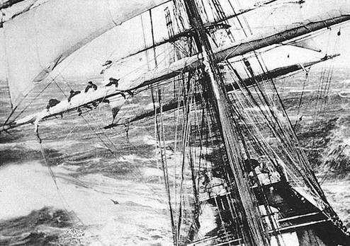
On this photo we can see, that the distance of the footrope is more or less parallel to the top of the yard arm - so it is looking maybe starnge, but the saftey of the seaman was important


 en.wikipedia.org
 en.wikipedia.org
Interesting, what I did not know before - the flamish horse
A Flemish horse is a footrope on a square rigged sailing ship that is found at the extreme outer end of the yard. The main footrope runs along the whole length of the yard, but because of its length the angle upwards to where it is attached is quite shallow, and thus it is too high to stand on for some distance inwards. Sailors on this part of the yard stand on the Flemish horse instead, which being shorter hangs down more and hence is low enough to stand on.


en.wikipedia.org

Take a look at this pdf, which may help in the execution and the planning
also nice to read

when we imagine, how many seamen have to be standing in the footropes to furl the sails .....
_manning_the_yards.jpg")
Yard (sailing) - Wikipedia
Footrope - Wikipedia
Interesting, what I did not know before - the flamish horse
A Flemish horse is a footrope on a square rigged sailing ship that is found at the extreme outer end of the yard. The main footrope runs along the whole length of the yard, but because of its length the angle upwards to where it is attached is quite shallow, and thus it is too high to stand on for some distance inwards. Sailors on this part of the yard stand on the Flemish horse instead, which being shorter hangs down more and hence is low enough to stand on.
Flemish horse (rigging) - Wikipedia
Take a look at this pdf, which may help in the execution and the planning
also nice to read
Foot-Rope Unity Kept 19th Century Seamen From Losing Their Balance
Foot-rope Unity Saved Shaky Seamen Serious Smackdown
www.scale-modelers-handbook.com
when we imagine, how many seamen have to be standing in the footropes to furl the sails .....
The french frigate replica Hermione is purely hand sailed, so no use of any winches


 lacigogneetlecaribou.kazeo.com
On cargue les voiles sur la frégate Hermione
Les gabiers finissent de carguer la grand'voile ...
- Joined
- Jan 15, 2021
- Messages
- 40
- Points
- 93
Thanks for the comments and pictures, I'm getting a better understanding of the relationship between yards and foot ropes.
To my way of thinking the basic idea is that for the sailors to carry out the required sail operations when they are out on the yards the height between the top of the yard and he foot rope needs to be the same regardless of the thickness of the yard. So for the main yard the foot rope should be closer to the yard than for a topgallant yard.
The yard diagram from Lennarth Peterssons book "RIGGING PERIOD SHIP MOD3LS" shows foot ropes different distances below the yards with the main yard foot ropes much lower than the topgallant foot ropes in relation to the top of the yard. I have marked up this drawing in red with revised foot ropes so they are all about the same distance from the yard top.
This significantly changes the height of the foot ropes on some of the yards.
Looking at the illustrations that have been posted in reply to my original query this seems to have some validity as foot ropes are shown quite close to larger yards.
Any thoughts before I start assembling yards with the revised foot rope positions. f
f
Cheers, David.
To my way of thinking the basic idea is that for the sailors to carry out the required sail operations when they are out on the yards the height between the top of the yard and he foot rope needs to be the same regardless of the thickness of the yard. So for the main yard the foot rope should be closer to the yard than for a topgallant yard.
The yard diagram from Lennarth Peterssons book "RIGGING PERIOD SHIP MOD3LS" shows foot ropes different distances below the yards with the main yard foot ropes much lower than the topgallant foot ropes in relation to the top of the yard. I have marked up this drawing in red with revised foot ropes so they are all about the same distance from the yard top.
This significantly changes the height of the foot ropes on some of the yards.
Looking at the illustrations that have been posted in reply to my original query this seems to have some validity as foot ropes are shown quite close to larger yards.
Any thoughts before I start assembling yards with the revised foot rope positions.
fCheers, David.
- Joined
- Jan 15, 2021
- Messages
- 40
- Points
- 93
I have been working on the yards and have fitted foot ropes and blocks and they are now finished. I made up the footropes as the marked up diagram to maintain the same distance from the top of the yard to the foot ropes and I think they look OK.
Cheers, David.

Cheers, David.