HMS BLANDFORD POF by Richard

Joined
Jul 24, 2016
Messages
96
Points
78

Hi Guys
Started my HMS Brandford 1:48 about 4 weeks ago
Brandford was the first in long series of similar ships, equipped with oar was a steppingstone between galley type frigates and true frigates from 1750
The sheer number of superbly laser cut parts is quite astonishing.
Each Frame is made up of 15 ribs which are laid in two layers as on a real ship There are 64 Frames which means nearly 1000 parts on the frames alone
My kit came with the Jig badly cut but I contacted the company, and a new Jig was sent from Chine and arrived a week later - MOST IMPRESSIVE

I will post a suggestion of building these frames as they need to be very accurately constructed
The keel again come in a number of parts as per a real ship and even has a False Keel (Which on a Fullsize ship allowed damage to be minimalist in the case of running aground. this is partially built in the jig to allow accurate placing of the parts

WeChatImage_20220227112513.png
 
Last edited:
been building wood model ship for over 60 years. First was the Norske Lowe by Billings - not a good kit but then bought the Panart Victory. REally incredible the Frames where cut and an amazing model was built - sold at Sotherby's after 5 years of building - deposit on my first house
 
Last edited:
Hallo @richardjjs
I am looking forward to see your work on this highly interesting kit.
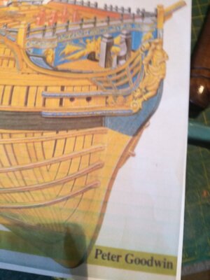
Do you have already the Anatomy book written by Goodwin? It could be of big help....
BTW1: I guess you mean scale 1:48 and not 1:200
BTW2: just realized, that in the advertisement is also written Brandford
 
Hallo @richardjjs
I am looking forward to see your work on this highly interesting kit.
Do you have already the Anatomy book written by Goodwin? It could be of big help....
BTW1: I guess you mean scale 1:48 and not 1:200
BTW2: just realized, that in the advertisement is also written Brandford
thanks all corrected
 
Seems i didnt take enough photos of the keel as i laid it down
I build up the stern and part of the bow
Little disappointed with the way the bow joins into the keel -t need a bit of cutting but it does fit

The keel allows to bottom frame to slot in with very little sanding and the stren just fits
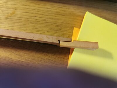
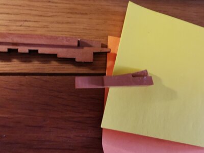
I fitted the stern to the keel and used masking tap to ensure it did not move - there are three slots in the base that the keel slots into
Fitted this without the false keel and lined the bow parts up
Then removed the keel and fitted the false keel which need Scarfe joints and 4 5 pieces of the special wood
This was taped while it dried and the keel fitted into the Jig
I then added and fixed the Bow section
Note the Hog or Rising Wood is not fitted till later in the construction but is Shown on the PLan - its the piece AT THE TOP OF THE BOW WITH A HOLE for the mainstay collar
I will post a photos of the keel before i attach the frames

IMG_20220827_183749.jpg

IMG_20220827_183807.jpg
 
The Frames
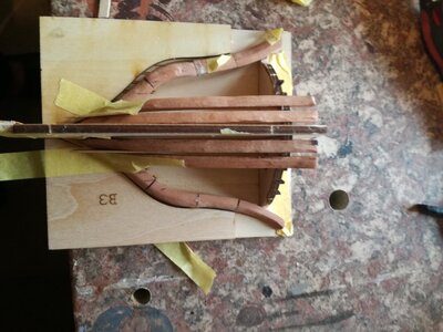
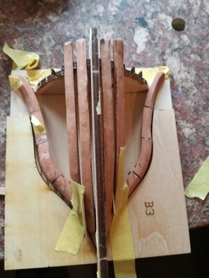
Each of the 62 Frames has a separate plane
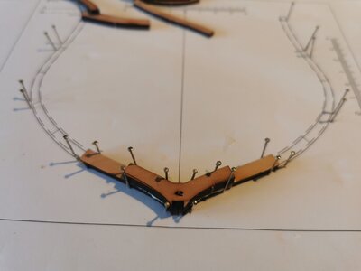
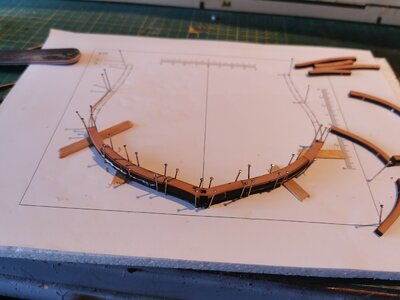
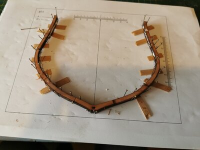
I used a flat piece of Foam to make a jig out of the plans and used pins to secure the parts os i built the frame
BUT some of them moved so I am now just laying 2 pieces on each side and gluing them so i ensure they dont move
The bottom 3 ribs MUST BE LAYED carefully using the jig to ensure they are level
I put the two pieces down first and the linking piece on to Photo 1

Leave it over night and then lay the next two on either side placing strips of 1,mm wood under them to ensure proper spacing - this is the reason it build it the other way to the instruction as you only need 1 set of spacers as you work up the frame Photo 2
Finally lay the next two ribs on either side
Finally fixing the small piece at the top

Everything should line up correctly

Take your time this is the most critical stage of the build

Each frame will be sanded in the next post

IMG_20220915_152656.jpg

IMG_20220915_153222.jpg

IMG_20220916_100022.jpg
 
Very Nice - I like the foam idea. Just as a side note, I used a plate glass as it held under 'downward' pressure and did not move around so much. The glass also helped in putting the plan underneath the glass so that I could glue directly 'to' the glass. However, nothing wrong with your method - it is a good method and I have to remember this one for sure. Thank you for sharing your build.

ps. I am sure with your experience that you are familiar with how laser-cut parts always produce an angle of the part. The effect of this can be observed by the fact that the 'joined' frame parts are 'snug' on one side, while there is a 'gap' on the other side of the part. The problem with sanding or filing those parts down so that 'both' sides are flush is that it WILL affect the overall dimensions of the completed single frame - we all know that errors will accumulate. So, you might want to be watchful to not file too much. I just made sure that one of the sides was joined tightly and did not worry about the gap on the other side.

However, let me say this clearly, you and others might have a different opinion and idea - and that is ok. Just stick with one trajectory and stick with it. I am sure that you will produce a fine model.

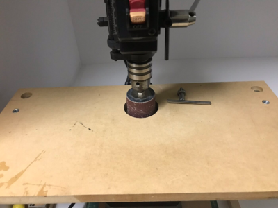
Also, I am sure that you are familiar with this, and if you are my apologies in advance, but this is what I used to remove the burned laser char from the parts. I bought a drum sander kit from Harbor Freight and built a level platform so that part will lay on its side flat and ran the part past the sander - However, this method ONLY is to remove the char - as you know the frames will be 'faired to shape'.

1663426815050.png
 
Last edited:
Very Nice - I like the foam idea. Just as a side note, I used a plate glass as it held under 'downward' pressure and did not move around so much. The glass also helped in putting the plan underneath the glass so that I could glue directly 'to' the glass. However, nothing wrong with your method - it is a good method and I have to remember this one for sure. Thank you for sharing your build.

ps. I am sure with your experience that you are familiar with how laser-cut parts always produce an angle of the part. The effect of this can be observed by the fact that the 'joined' frame parts are 'snug' on one side, while there is a 'gap' on the other side of the part. The problem with sanding or filing those parts down so that 'both' sides are flush is that it WILL affect the overall dimensions of the completed single frame - we all know that errors will accumulate. So, you might want to be watchful to not file too much. I just made sure that one of the sides was joined tightly and did not worry about the gap on the other side.

However, let me say this clearly, you and others might have a different opinion and idea - and that is ok. Just stick with one trajectory and stick with it. I am sure that you will produce a fine model.

Also, I am sure that you are familiar with this, and if you are my apologies in advance, but this is what I used to remove the burned laser char from the parts. I bought a drum sander kit from Harbor Freight and built a level platform so that part will lay on its side flat and ran the part past the sander - However, this method ONLY is to remove the char - as you know the frames will be 'faired to shape'.

i decided not to remove the char. this then allows me to use the sander hand help and the char alloiws me to work out what ive sanded so far4
photos follow
 
I am writing a set of instruction for VIctor - Just the frames so far
Hi Richard,
In your instructions you talk about 'ribs' as parts of the frames, do you mean futtocks? And when you are attaching the 'A' and 'B' halves are their faces opposite each other? i.e. facing forward and aft.

Regards JJ.
 
Hi
The instruction refer to the "Bits" of the frames being called ribs so i use that term but it would appear that the correct term is Futtock
ie Each timber is made up of 4 sometimes 5 futtocks for each timber and 2 sets for what i suppose would be a complete frame
Thanks you for pointing this out - I will include this in my instructions
Yes there are two halves to each frame and the markings on the futtock should be visible to allow the completed frame to be properly shaped
There is probably a special term for this shaping

IMG_20220916_160348.jpg
 
Hi
The instruction refer to the "Bits" of the frames being called ribs so i use that term but it would appear that the correct term is Futtock
ie Each timber is made up of 4 sometimes 5 futtocks for each timber and 2 sets for what i suppose would be a complete frame
Thanks you for pointing this out - I will include this in my instructions
Yes there are two halves to each frame and the markings on the futtock should be visible to allow the completed frame to be properly shaped
There is probably a special term for this shaping

View attachment 330854
Thank you for the clarification Richard, I never heard of any parts of frames called 'bits' so maybe that was lost in translation. I think the shaping of the frames is called fairing. Good luck with your build, looks like you have made a great start. JJ.
 
i put bits in inverted commas because i was trying to explain the separate bits or pieces of the frame.
But yes bits was my term
 
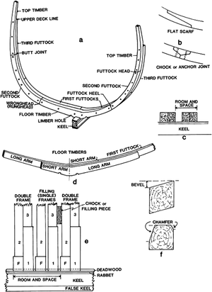
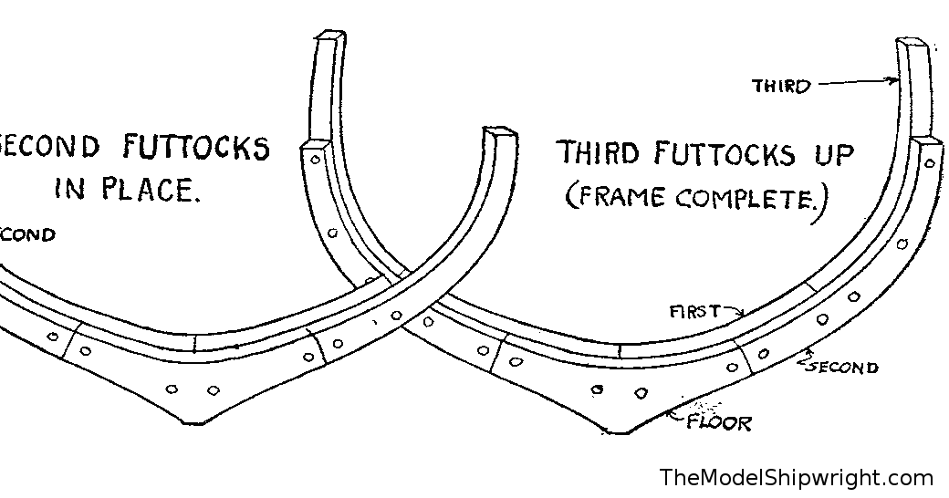
This sketch is helping to define the correct terms of the frame elements

oxfordhb-9780199336005-graphic214-full.gif

So a frame contents the
- Floor timber
- several futtocks
amd
- the top timber

The term Fairing is used, also used Beveling


Very helpful:

Illustrated Glossary of Ship and Boat Terms

by J. Richard Steffy

this glossary is for free download or web-use and is part of "The Oxford Handbook of Maritime Archaeology"

check it out:

http://www.oxfordhandbooks.com/view...99336005.001.0001/oxfordhb-9780199336005-e-48
 
that is really helpful - thanks
Some of my pictures show scarf joints on the futtocks =but this is the way the model is assembled
It would be useful to know what the pins are that join the futtocks together
 
that is really helpful - thanks
Some of my pictures show scarf joints on the futtocks =but this is the way the model is assembled
It would be useful to know what the pins are that join the futtocks together
Usually these were metal bolts
frames.jpg

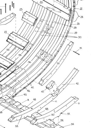
Very interesting and helpful, and close to a "must have"-book

and for the Blandford modelers

and for french ship builders - here you can find some pages showing the imense number of iron bolts used on a 74 gun ship - up to 70 tons of metal for bolts was used in such a ship of the line
 
Last edited:
BUILDING THE BOW
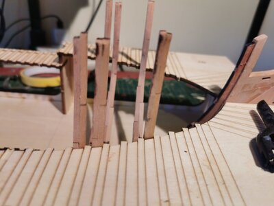
Having a few problems with the bow
Looking at various books and plans it looks as though the Hawse Frames have too big a gap between 6 and what is called the No 1 Square Frame
I am going to remove those little pieces on the the jig from 3 onward (1 is missing alreadt and move the next few hawse frames squarer to the jig and Frame 1
A slight touch of glue to fix it for now
All the books i have show that no 6 Hawse uch nearer to frame 1 than the model

Will take some better photos of the diagrams
The instructions are really not good as i somehow mixed up right and left


IMG_20221009_144214.jpg

IMG_20221009_144240.jpg

IMG_20221009_144245.jpg

IMG_20221009_144256.jpg

IMG_20221009_144524.jpg
 
Last edited:
BUILDING THE BOW
Having a few problems with the bow
Looking at various books and plans it looks as though the Hawse Frames have too big a gap between 6 and what is called the No 1 Square Frame
I am going to remove those little pieces on the the jig from 3 onward (1 is missing alreadt and move the next few hawse frames squarer to the jig and Frame 1
A slight touch of glue to fix it for now
All the books i have show that no 6 Hawse uch nearer to frame 1 than the model

Will take some better photos of the diagrams
The instructions are really not good as i somehow mixed up right and left


View attachment 333347

View attachment 333348

View attachment 333349

View attachment 333350

View attachment 333351
Did you check the building log of our friend @Keef ?

Please take a look at this post and the following showing very good, how the bow structure should be done
 
Back
Top