HMS Druid P.O.F. - Unicorn Models by Donnie [COMPLETED BUILD]

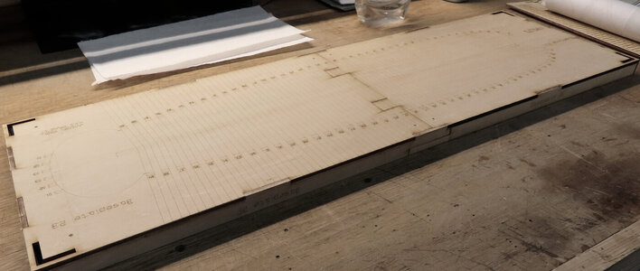
So, the bottom half is finished.

jig-08.jpg

jig-09.jpg


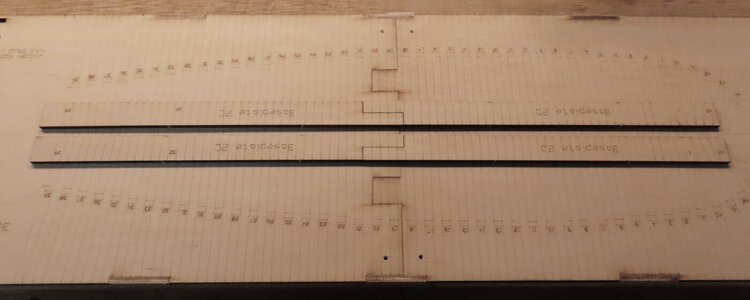
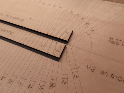
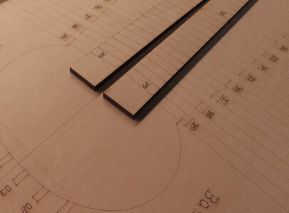
What I like especially are these two strips that keep the Keel in line and fixed in position. The strips also have the laser scoring on it too. They will be glued in place when the Keel is built.

jig-10.jpg

jig-11.jpg

jig-12.jpg


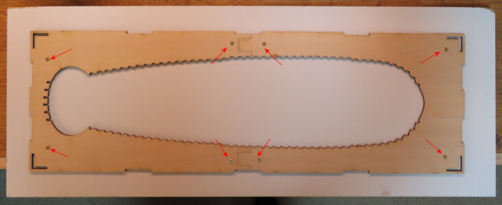
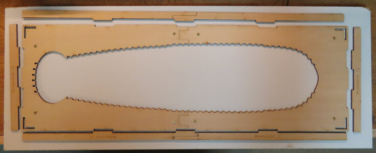
Now this image is where I am starting the Top half of the Jig. Following the same procedure. Red Arrows shows where I am using screws to secure the Jig Top. The Jig Top gets flipped upside down because the supports will be glued to that forming (again) a lid style container. The screws are only temporary.

jig-13.jpg

jig-14.jpg
 
Hi Daniel,
well, I am glad that my efforts are worth it then if someone can benefit from it. I thought I was the only one that had the Druid. Maybe you can start yours soon too.

Donald
 
Thanks for sharing Donnie. Your detailed step by step gives one a better appreciation for how the big boys play. Will just be quietly watching on the sidelines as I am still quite a ways from being ready to tackle an advanced build such as this. Keep safe.
 
Hello Donnie,
Nice to see the start of another PoF build on a Jig. The jig shows, ZHL has put a lot of attention to this part and it will give a lot of help during the build.
Regards, Peter

Ad-on 30-12, see below: Thanks to Dave, it is not from ZHL but from Unicorn Models.
Regards, Peter
 
Last edited:
Hi Daniel,
well, I am glad that my efforts are worth it then if someone can benefit from it. I thought I was the only one that had the Druid. Maybe you can start yours soon too.

Donald

Hi Donald

I am very busy with my Statenjacht PEGASUS. It is taking me more time than the one I imagined. I also saw I have new gray hair due to the stress building such kit. :) (something we used to said among friends when we were stressed- "you have now more gray hair") :)

Moreover, my oldest son (35 YO) requested me to built THE TURTLE . A Korean War ship. I got the kit from a Korean seller (English instructions). It is a detailed kit with the interior.


And after The Turtle, I could plan to start the Druid at some point late in 2021 now that you are doing this building log.

Cheers !!
Daniel
 
Good to hear that you plan to do so, and that you also have a lot of projects going on. I envy those that can do multiple projects at the same time. Seems I can only focus all my energy on one !!! LOL

Well, at any rate, here I am and I have the full box assembled. Ignore the Machinist Square as it does show a little off on the 90° upright support. Things are not adjusted just yet. DO NOT GLUE THE UPRIGHTS SUPPORTS JUST YET - - WAIT

EDIT: I highly suggest waiting until you have a few Frames constructed BEFORE you glue all the upright supports. Not only does the "Fore and Aft" position of the Jig Box needs to be fine-tuned, but also the Port and Starboard fine-tuning of the Box needs adjustment as you also want the Frames to sit correctly in that fashion too. PLEASE review and you can skip ahead to POST #32 for a detailed CAD drawing.
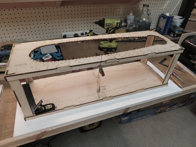
jig-15.jpg

NOTE: AT THIS POINT, DO NOT GLUE THE SIDE SUPPORTS. I will explain it.

The reason is that when I first assembled the side supports and set the box upright, the first thing I did was to grab my Plumb line. To my (sinking feeling that I had), I noticed that the Plumb was NOT lined up correctly on the FRAME NUMBERS.

For instance, I would put the Plumb Line on the Top edge of the Jig (let's say at #17 which is about a good halfway point, THEN I could not believe that the Plumb was resting at the MIDDLE of #17 instead of at the edge of #17 which it should. I could not figure out what was wrong. It was like the upper (or Lower) jig was shifted about 2.5 mm. This can't be.

So, since I did not glue the side supports, I took them out so that I could lay the two half boxed Jigs on top of each other to see what the alignment problem was. . . was it that one Jig was actually longer or shorter? Well, the two Jigs DID line up --- well, that was a relief, so how come it did not line up with the box fully built?

I reassembled the upright supports. I guess somehow, reassembling the upright supports and wigging the box back and forth a little, it must have "settled" in better.

So, I secured the Plumb with a clamp. I then moved the box very slightly from side to side (left to right) until the Plumb line was right on target - then - I will now glue the uprights and while the glue is wet, then, fine-tune the box for Plumb and let the Glue set up. I found out that it takes VERY Little movement (side to side) on the Jig Box for the Laser print alignments (at the Top and Bottom) to be off as much as almost 3 mm. This is not good of course, as you want a good 90° verticle alignment with the Frames. If you were to use a little math Trigonometry to see that only a .5mm side to side movement of the Top Jig will equate to a large like 2mm offset at the bottom. This is due to the height of the box. The taller the box, the more exaggerated offset can be with just a tad of offset at the top.

The picture below shows the upper and lower JIg and how the Plumb line is now correct. But, I shall go back and double-check some other frame numbers to see how they are. Then I took my machinist square and checked the upright supports and all seems to be 90° square there as well too.
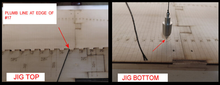
jig-16.jpg
 
Last edited:
Hi Donnie,
I will follow your build with great attention to all provided detail! Thanks for spending the time to explain each step in a concise yet detailed manner. This will be a great learning experience and hope to apply in my efforts accordingly.
Thanks brother!
Dan
 
Hello Donnie,
Nice to see the start of another PoF build on a Jig. The jig shows, ZHL has put a lot of attention to this part and it will give a lot of help during the build.
Regards, Peter

i may be wrong here but ZHL does not produce the kit it is done by Unicorn models, ZHL is just a distributer like a hobby shop.
 
correct Dave, my mistake in listing it like so - I need to change that asap. Yes, to all. This is a Unicorn Models kit that so happens that ZHL "carries" the kit.
 
Last edited:
Not having built a POF kit, it is not obvious to me, and may not to others, but it is just a good practice to check. For me, it is very easy to get way ahead of myself and NOT check things but overlook the OBVIOUS. To others, this might be second nature, but to me, it might not be.

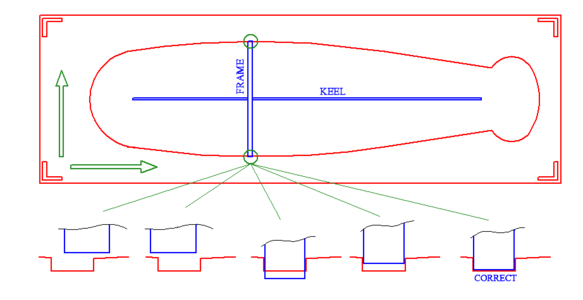
So, therefore, I created a drawing [of the TOP Jig part] for those that might follow this log when they decide to build this kit themselves.

The GREEN arrows show in the manner that you MIGHT need to shift the box VERY slightly to obtain corrected orientation of the Frames so they sit correctly in the KEEL while touching each side of the Jig appropriately and not have any major Gaps. The drawing does NOT show the Frame Notches for simplification of the example.
This is why you might want to build a few Frames first and fit them into the Jig first before finally gluing down the upright supports !!!!

This may seem very elementary to some, but I continue to help those that might consider this problem.

1609352903494.png
 
Last edited:
i may be wrong here but ZHL does not produce the kit it is done by Unicorn models, ZHL is just a distributer like a hobby shop.
correct Dave, my mistake in listing it like so - I need to change that asap. Yes, to all. This is a Unicorn Models kit that so happens that ZHL "carries" the kit.
When I have looked better to the picture of the front of the box, I also could have seen it was a kit of Unicorn Models.
My I apologize. I am glad we have Dave!
Regards, Peter
 
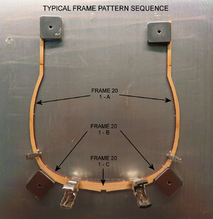
VERY IMPORTANT NOTE: Not all individual frame (or rib) pieces are located sequentially. For example, the 9_2B frame piece is located on the board that has the 20 series frame pieces. In other words, when I was cutting out the frame pieces for FRAME #9, not all the #9 pieces are on the same board, but some are scattered around on other boards.

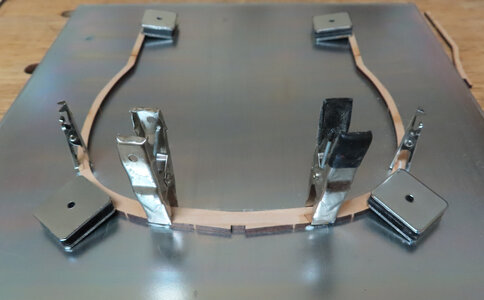
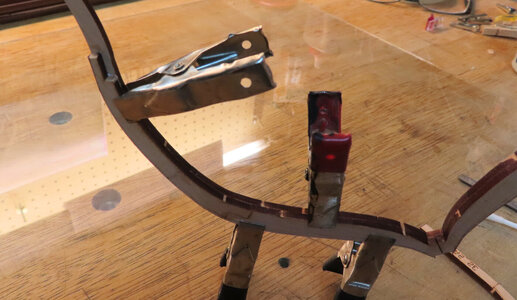
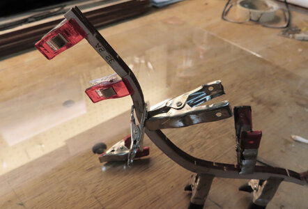
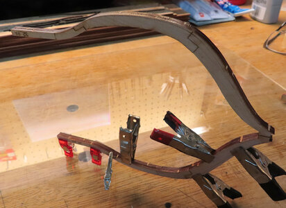
Ok, so I put the Jig to the side - enough of that. It is time to start making some Frames and I am starting with Frame #20. The frames are cut out of the laser cut boards and are easy to remove taking the fact that just a little cutting from an Exacto will remove them. The Frames are not single frames but are doubled/layered on top of each other. The Frames are 3mm or 7/64 inches thick and it only takes a small alligator clip and a small clamp to hold them. I only have one piece of thin double-sided tape and that is to hold the 'base" of the Frame steady while I glue them.

This first half of the Frame has the "Floor Timber" at the Keel Notch and will face the BOW. This follows convention. There is a reference mark on the backside of this that I will show later.

20-A-02.jpg

20-A-01.jpg
 
Last edited:
I can show you the parts laid out next frame. Unless the plans were omitted somehow, there are no plans or drawing to lay the patterns over !!! I am just letting the natural joints (from laser cut) follow the natural path. The way the joints are made, it is almost impossible to make them crooked or any other way.
 
Last edited:
In my haste to make one frame, I realized that I did not show the sequence of how I did this. Ops. I will do that today. So, I made another Frame which is #8. It is halfway between #20 and the bow - I just chose this one as I want to continue to check the alignment of the JIg and I thought if the Frames were spaced out enough, I can get an idea of how things are lining up and then I will glue the Jig Uprights. In the meantime, I built Frame #8 differently. I put together each half completely, then I glued each half together. This way is a lot more trouble trying to keep the "halves" align while I clamp it down.
I will go back to the first way and that is: I made the Frame that has the Full Floor Timber first. Then I glued each individual part to the other frame one piece at a time. I will show you later. Sorry for not demonstrating pictures of this important step.
 
I will now try to show you the work-flow since the kit does not provide any templates or patterns to go by for the construction of the Frames. The Frame pieces have notches or interlocks in some way which really facilitates a nice way of building up a frame without the need of a template to overlay.

Here is the workflow of each frame: You MUST make sure that all Lazer reference lines and fairing lines are on each OUTSIDE frame pieces and do not cover those up. Make sure they are on the outside. Here you will see the frame is laying with its real "face" face down on the metal plate.

VERY IMPORTANT NOTE: Not all individual frame (or rib) pieces are located sequentially. For example, the 9_2B frame piece is located on the board that has the 20 series frame pieces. In other words, when I was cutting out the frame pieces for FRAME #9, not all the #9 pieces are on the same board, but some are scattered around on other boards. I have already found several instances where some of the parts to a frame are on separate pattern boards.


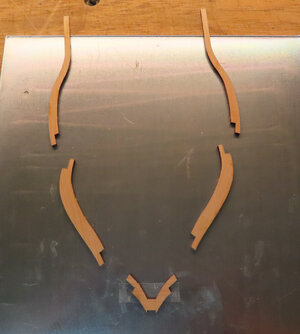
SELECTION OF PARTS.
NOTICE THE DOUBLE SIDED TAPE HOLDING THE FLOOR TIMBER IN PLACE.


work-flow-01.jpg


STARTING TO GLUE UP PARTS. SMALL ALLIGATOR CLIPS ARE USE AT THE JOINTS. THE JOINTS SEEM TO AUTOMATICALLY ALIGN THE FRAME CORRECTLY.

work-flow-02.jpg


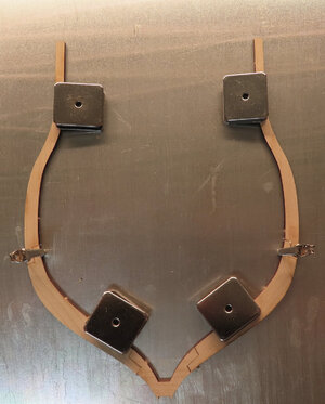
A METAL PLATE IS USED WITH SOME MAGNETS TO HELP HOLD FRAME IN PLACE, BUT IT IS NOT REALLY NECESSARY. THE MAGNETS ARE ONLY USED TO MAKE SURE THE FRAME LAYS FLAT TO SURFACE.
work-flow-03.jpg


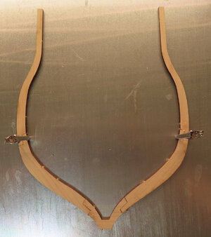
THIS SHOWS THE FIRST FRAME PIECE - JUST OVERLAY THE FRAME TO THE OTHER FOR A GUIDE. (SIMPLE). YOU CAN SEE THE THE FAIRING LINES AND REFERENCE LINES ARE ON THIS OUTSIDE EDGE. WHEN YOU FLIP THE FRAME OVER ON EACH SIDE, YOU WANT TO BE ABLE TO SEE ALL YOUR REFERENCE LINES AND FAIRING LINES - DO NOT COVER THEM UP BY REVERSING THE FRAMES SECTIONS.
work-flow-04.jpg


CONTINUATION OF THE SECOND PIECE. THE OTHER JOINT CLOSES NICELY AND FITS WELL ALL ALIGNING WELL.

work-flow-05.jpg


CONTINUATION OF THIRD PIECE

work-flow-06.jpg


CONTINUATION OF FOURTH PIECE (ON OTHER SIDE)

work-flow-07.jpg


CONTINUATION OF FIFTH PIECE (ON OTHER SIDE)

work-flow-08.jpg


CONTINUATION OF SIXTH PIECE (ON OTHER SIDE)

work-flow-09.jpg


THE FRAME IS COMPLETELY GLUED UP AND CLAMPS WILL BE RELEASED AND THEN GO TO THE SPINDLE SANDER TO CLEAN UP CHAR.


work-flow-10.jpg


SO, THIS ENDS THE WORKFLOW AND NO NEED TO REPEAT FOR EACH FRAME UNLESS THERE IS A SPECIAL NEED OF SUCH.

Enjoy !

Donald


----------------------------------------------------------------------------------------------------------------------------
EDIT 1/24/2021:
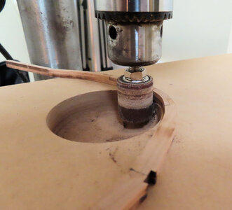
I forgot to mention that I use a spindle sander attachment on my drill press to sand off the char.

work-flow-11.jpg


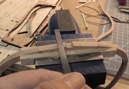
I AM SHOWING FILING THE NOTCH AND CLEANING THOSE OUT FOR EACH FRAME. I AM USING THE FLOOR JOINTS TO LINE UP THE FRAME SO I HAVE A GOOD FLAT REFERENCE TO GO BY (INSTEAD OF JUST PUTTING FRAME IN VISE). THIS WAY, I CAN ALSO TAKE A FLAT SCRAP OF WOOD AND LAY IT ON THE JAWS OF VISE TO SEE IF NOTCH "BOTTOM" IS FLAT.

work-flow-12.jpg


ON SOME FRAMES, I AM COMPARING THE FRAME #1 WITH ANOTHER FRAME TO SEE IF THE "FLAT" AT BOTTOM FLOOR IS CONSITANT WITH THE NEXT FRAME. THIS ONLY TAKES A COUPLE OF MINUTES TO CHECK.

work-flow-13.jpg


THIS SHOWS ABOUT A LITTLE THAN HALF THE FRAMES COMPLETED AND CLEANED UP SOME.

work-flow-14.jpg
 
Last edited:
Just for those that might not be familiar, but laser cutting is not exactly at 90° - but cuts through the wood at a slight angle in most cases, this is not such a problem. But in the case of the top jig cut-outs, the individual frame (rib) cutouts need to be filed at 90° so that frames (ribs) will rest perpendicular to the base.
It is not necessary to file the frame joints - however at the top of the jig where the frame or rib alignment notches DO NEED this so frames will fall into a nice 90° alignment to the base.

1609635071153.png
 
Back
Top