HMS GRANADO (1742) - midship section - POF by CAF in 1:48 - by Uwe

Uwek

Administrator
Staff member
Administrator
Forum Moderator
Joined
Dec 25, 2017
Messages
31,112
Points
1,238

Location
Vienna, Austria
Some days ago I started working on a new project -

HMS GRANADO - bomb vessel
midship section - POF
by @CAFmodel in 1:48

I made already a detailed kit review, where you can find more detailed Information abou the content and also the specialities of this kit, like the correct framing, the new kind of jig, using boxwood for the complete structure etc. -> so in my opinion a very special kit


In the following only some photos of the finished CAF model so you get an impression what you can expect.

I have chosen this project, because I plan to finish it until end of this winter, so I am able to take it with me to the planned modelers come together in Augsburg, Germany in March 2022. Let us see, if this will work

02.jpg


327f9f5936.jpg


The kit was offered directly via CAF-web-page


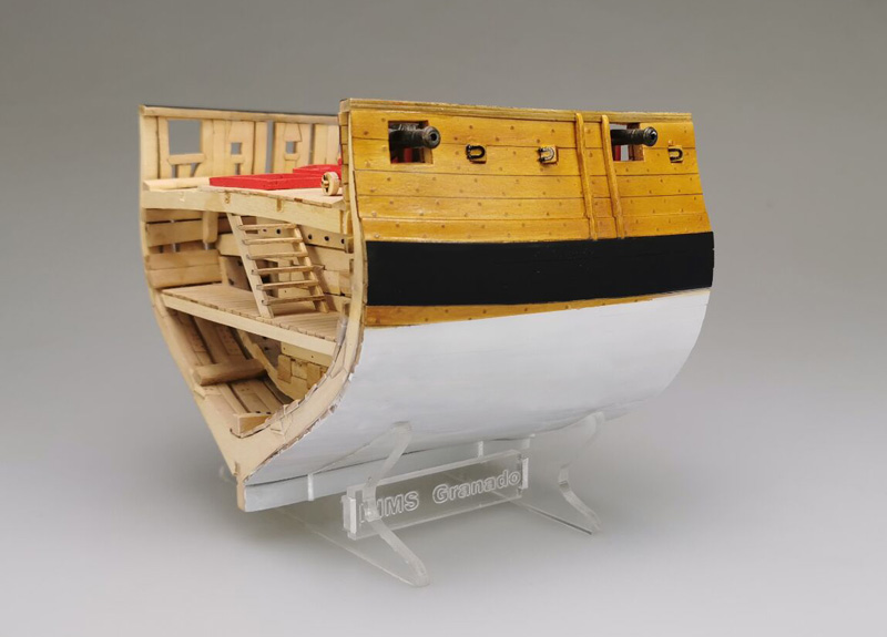
The size of the CAF model in scale 1:48 when finished completely

0d32c42357.jpg


In order to complete the available topics related to Granado and the kit(s) in SOS:


so stay tuned - in short time I will show you the first working steps in my detailed building log
 
Ha Ha - I am also excited - and I can tell you already that building this model brings a lot of fun - with fast success and visible progress in short time
The big advantage of section models - only some frames and you have already your hull finished ...... but step by step

First of all for all your information.... I made today a topic in the ship history area showing in more detail the vessel HMS Granado 1742 and also contemporary resources, data, drawings, models etc........

 
Before I start to show the "real" work on the model, just some additional information.

CAF produced with this kit (according to my knowledge of the market) the first time a POF- framing like the real ship was made.
with the reduction of the thickness from the floor timber up to the top timbers, and also with the twisting at the top timber near the gunports and / or the oar-ports

Here you can see the frame timber plan made by Goodwin - the red lines enclose the section of the Granado kit
IMG-5207.jpg

a closer look
IMG-5207a.jpg

and here the test model from CAF showing all the frames of the section
119.jpg

Here a 3D-animation from CAF showing two double frames - red and green are the frame elements with floor timbers, futtocks and top timbers, in grey colour are shown the anchor chocks connecting the elements with bolts
36.jpg

37.jpg

to illustarte also with the help of Goodwins sketch - and the kit is completely following this principle structure

IMG-5211.jpg
 
Many Thanks to all for the kind words and the likes already received (although I did not show anything of my own work ;) )

IS THIS THE ONE WITH THE PLEXIGLASS JIG INTRIGUING
Hallo Don, Yes, it is the model with the plexiglass jig - you will see it soon

Looks interesting. I read your kit review, visited CAF's site - no word on wood used. Castello? Or something else?
I mentioned it in the kit review already - the used wood, somehow yellow, is very close to boxwood, either in colour (only very small color differences between the sheets) but also in the behaviour. Much harder than pear or cherry, with a very fine grain. So sanding takes more time, but you can work very accurate and you can acchieve very accurate edges - The used "boxwood" wood is one speciality of this kit and makes it also very special - and I am pretty sure also more expensive in the production, also because of the necessary use of much thicker wooden sheets (compared to other kits) caused by the cnc-cutting

IMG_6167a.jpg

IMG_6192.JPG

Take a look here:

 
In the following you can see some two more sketches from CAF which are helping to understand the structure and building of the individual frames

The frames are numbered 6 to 14, so all together 9 double frames. Every double frame consists on a side named "B" (dark blue) and also "A" (light blue)

IMG-8076.jpg

The "A"-side is every time the direction via the bow of the vessel

IMG-8077.jpg

For each frame we can find a frame drawing which have to be used for the correct alignment of the frame elements

IMG-5601.jpg

The manual is starting with frame "6"

The (green) filler elements 1A-1 which has the same form like the top timber (5F-6B-6) are only temporary, in order to get the small step over the height of the frame (here from second futtock to top timber). These filler parts should be fixed with glue to the plans. A hatched area on each frame drawing indicates where they fit.

IMG-8079.jpg

Here you can see the drawing with all wooden parts of side "B" of frame "6". The correct part numbers are shown in the sketches of the manual, you can find a parts plan in the rear of the manual. The parts number have to be marked with pencil on the wood, you don't want to mix them up.
Short explanation to the numbering:
f.e. 5F-6B-4 (see the photo before)
5F - is the sheets number - here btw 5 indicates the thickness of the wooden sheet 5 milimeter
6B - is for frame "6" side "B"
4 - is the part number of the individual frame side

IMG-7890.jpg

after finishing and gluing side "B" you should install side "A" on top of the side "B"

IMG-8089.jpg

Now I came to the point, that I understood completely the way and methods used with the filler elements, the temporary resin inserts (which you will see later)......
but .....
I was not sure which lines to follow on the drawing ????
Red for "B" or is it black for "B" ..... or?

Tomorrow I will show you in detail how I solved it - btw correctly
 
I am working currently on the same kit. It took me some time to figure out which line was up to.

So, red line is for "B" and the upper black line for "A".
Ha...!!! You are working on the same kit, how about you starting the build log? Is it feasible? It will be great for our members, thought.
 
I am working currently on the same kit. It took me some time to figure out which line was up to.

So, red line is for "B" and the upper black line for "A".
Many Thanks for the information.
I am very happy to read, that you are also working on this interesting kit.
Knowing your great model of the Bonhomme Richard section, I can also full underline the words by Jim -> it would be great to see also your work on the Granado in a building log...... would be great
Just found your log you started already before I wrote my last post - Many Thanks
For everybody interested, take a look here:
 
Due to the fact, that it was hard to understand the shown lines on the drawing of frame "6" I decided to check the situation with the frame "14", on the oposite end of the section. Here we have also the biggest difference of the lines due to the biggest fairing of the frames

IMG-7901.jpg

The drawing of frame "14" is on the second sheet of drawings, the only frame on the sheet, and here we can find also this small skecth with coloured lines and and arrow, which is explaing the order

IMG-7904.jpg

IMG-7908.jpg

IMG-7909.jpg

so the outside of Frame-side "B" has to follow the red line and frame-side A the purple one / the bearding or fairing line markes on the wooden parts

IMG-7906.jpg

view streight from the top

IMG-7907a.jpg

and the manual is showing the stucture of the "14"

IMG-8080.jpg

IMG-8081.jpg

This sketch might also help to understand
IMG-7910.jpg

But before we are able to fix the frame parts there is one additional preparation work necessary, which can be fastly prepared with a sharpe knife

IMG-8078.jpg

All frame parts are CNC routed, therefore all internal edges are rounded and have to be squared off. A sharp scalpel will do the job easily - you can see the difference before and after on the next photo.

IMG-7940.jpg


OK - let us do the first frame
-> a paper-copy of the frame drawing was fixed to a glass-plate and the parts aligned along the lines. Here "B" along the red line

IMG-7920.jpg


The first frame glued and prepared - and the system was understood

IMG-7932.jpg

IMG-7933.jpg

IMG-7935.jpg

to be continued ......
 
Hallo Uwe, you have started something, looks very nice. Is actually quite different from thr Le Coureur. I'm in.
Yes, it is different, but the framing works of the Granado has also several chellenges like the frames of the Le Coureur - it is highly interesting - a complete different POF feeling

I am not planning to bore you with every single frame in the following posts. But maybe it is interesting to see the works on frame "13" where one of the resin elements were used. Therefore I show you the working steps of this frame with the help of a photo-series.....

The floor timber and on each side the two temporary distancers

IMG-7937.jpg

IMG-7938.jpg

all elements prepared - at the top next to the top timbers you can see the resin parts for this frame

IMG-7939.jpg

IMG-7941.jpg

side "A" along the black line

IMG-7942.jpg

The resin element
IMG-7945.jpg

IMG-7946.jpg


side "B" on top of side "A" - and the resin distancer

IMG-7943.jpg

IMG-7947.jpg

IMG-7944.jpg

after removing from the plan - the back side of Side "A"

IMG-7948.jpg

IMG-7950.jpg

IMG-7951.jpg

the front side with side "B"

IMG-7949.jpg

IMG-7952.jpg

IMG-7953.jpg
 

Attachments

  • IMG-7938.jpg
    IMG-7938.jpg
    175.4 KB · Views: 13
  • IMG-7937.jpg
    IMG-7937.jpg
    177.2 KB · Views: 12
Back
Top