You are using an out of date browser. It may not display this or other websites correctly.
You should upgrade or use an alternative browser.
You should upgrade or use an alternative browser.
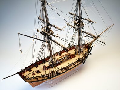
Vanguard Models new kit Hms Speedy 1:64
- Thread starter zoly99sask
- Start date
- Watchers 7
-
- Tags
- speedy vanguard models
Looking very good. Especially the huge number of photo etched parts and complete copper plating - could be really a nice and interesting built !
Unfortunately no photo of the fittings shown (anchors, etc.) and not of the planking strips - the deck planking is prepared as one piece and laser surface treatment to show deck-planking
Interesting to see, that Vanguard never rig the guns on their advertisement models
Unfortunately no photo of the fittings shown (anchors, etc.) and not of the planking strips - the deck planking is prepared as one piece and laser surface treatment to show deck-planking
Interesting to see, that Vanguard never rig the guns on their advertisement models
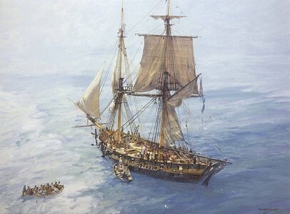
Fore everybody interested in the history of the original 14-gun HMS Speedy, launched in 1782:
HMS Speedy was a 14-gun Speedy-class brig of the British Royal Navy. Built during the last years of the American War of Independence, she served with distinction during the French Revolutionary Wars.
Built at Dover, Kent, Speedy spent most of the interwar years serving off the British coast. Transferred to the Mediterranean after the outbreak of the French Revolutionary Wars, she spent the rest of her career there under a number of notable commanders, winning fame for herself in various engagements and often against heavy odds. Her first commander in the Mediterranean, Charles Cunningham, served with distinction with several squadrons, assisting in the capture of several war prizes, such as the French frigates Modeste and Impérieuse. His successor, George Cockburn, impressed his superiors with his dogged devotion to duty. Speedy's next commander, George Eyre, had the misfortune to lose her to a superior French force on 9 June 1794.
She was soon retaken, and re-entered service under Hugh Downman, who captured a number of privateers between 1795 and 1799 and fought off an attack by the large French privateer Papillon on 3 February 1798. His successor, Jahleel Brenton, fought a number of actions against Spanish forces off Gibraltar. Her last captain, Lord Cochrane, forced the surrender of a much larger Spanish warship, the Gamo. Speedy was finally captured by a powerful French squadron in 1801 and donated to the Papal Navy by Napoleon the following year. She spent five years with them under the name San Paolo, but was struck around 1806.

 en.wikipedia.org

 en.wikipedia.org
 en.wikipedia.org
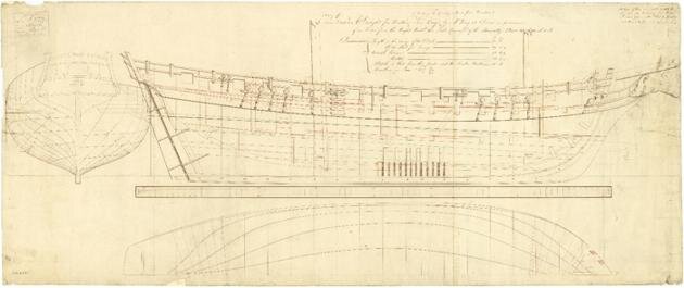
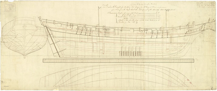
and in NMM available are some contemporary drawings
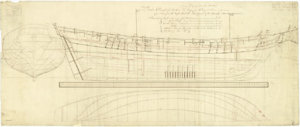
Lines & Profile (ZAZ4631)


Drawing; there are some ground for believing this is by Commander (later Vice-Admiral Sir) Jahleel Brenton (see Notebook field), who commanded 'Speedy' at the time. The style of the title given above suggests it may be written on the drawing (TBC): if so, it may be possible to check the MS against other examples of Brenton's. The 'Queen Charlotte', Howe's flagship at the Glorious First of June 1794, was accidentally burnt off Leghorn in 1800, with considerable loss of life. [PvdM 1/11]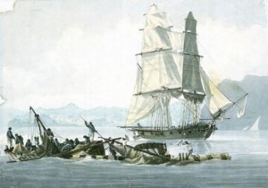


HMS Speedy was a 14-gun Speedy-class brig of the British Royal Navy. Built during the last years of the American War of Independence, she served with distinction during the French Revolutionary Wars.
Built at Dover, Kent, Speedy spent most of the interwar years serving off the British coast. Transferred to the Mediterranean after the outbreak of the French Revolutionary Wars, she spent the rest of her career there under a number of notable commanders, winning fame for herself in various engagements and often against heavy odds. Her first commander in the Mediterranean, Charles Cunningham, served with distinction with several squadrons, assisting in the capture of several war prizes, such as the French frigates Modeste and Impérieuse. His successor, George Cockburn, impressed his superiors with his dogged devotion to duty. Speedy's next commander, George Eyre, had the misfortune to lose her to a superior French force on 9 June 1794.
She was soon retaken, and re-entered service under Hugh Downman, who captured a number of privateers between 1795 and 1799 and fought off an attack by the large French privateer Papillon on 3 February 1798. His successor, Jahleel Brenton, fought a number of actions against Spanish forces off Gibraltar. Her last captain, Lord Cochrane, forced the surrender of a much larger Spanish warship, the Gamo. Speedy was finally captured by a powerful French squadron in 1801 and donated to the Papal Navy by Napoleon the following year. She spent five years with them under the name San Paolo, but was struck around 1806.

HMS Speedy (1782) - Wikipedia

Speedy-class brig - Wikipedia
HMS Flirt (1782) - Wikipedia
and in NMM available are some contemporary drawings

Lines & Profile (ZAZ4631)


Drawing; there are some ground for believing this is by Commander (later Vice-Admiral Sir) Jahleel Brenton (see Notebook field), who commanded 'Speedy' at the time. The style of the title given above suggests it may be written on the drawing (TBC): if so, it may be possible to check the MS against other examples of Brenton's. The 'Queen Charlotte', Howe's flagship at the Glorious First of June 1794, was accidentally burnt off Leghorn in 1800, with considerable loss of life. [PvdM 1/11]


Last edited by a moderator:
- Joined
- Oct 23, 2018
- Messages
- 587
- Points
- 353

The original drawing shows a quite interesting detail. Speedy was built only with single frames and not with the standard method of double and single frames.
Thanks for sharing, Uwe
Thanks for sharing, Uwe
Yes, @MarisStella will release a Speedy kit in 1:48 scale ,much bigger than Vanguard 1:64Do I remember right that some time ago some other builder was talking about offering the same model as a future release ??
here it is
MarisStella - New Kit - HMS Speedy 1:48
www.marisstella.hr/eng Maris Stella Ltd is pleased to announce the addition of the HMS Speedy, HMS Vensejo and HMS Sophie Brig-Sloops, in 1:48 scale, to its model ship kit line. Speedy and Vensejo have been heavily researched. HMS Sophie is our version of the fictional Brig-Sloop, representing...
shipsofscale.com
- Joined
- Mar 2, 2012
- Messages
- 112
- Points
- 103

Looking very good. Especially the huge number of photo etched parts and complete copper plating - could be really a nice and interesting built !
Unfortunately no photo of the fittings shown (anchors, etc.) and not of the planking strips - the deck planking is prepared as one piece and laser surface treatment to show deck-planking
Interesting to see, that Vanguard never rig the guns on their advertisement models
I have my HM Speedy in my hands. I ordered it on a Saturday and had it the following Wednesday.
The anchors are standard cast metal, the cannons are resin and very detailed, much more than cast cannons. The carriages are the standard layered parts. The planking strips are standard lime wood first planking, but the parts and all 2nd planking are pear wood, it looks exceptional and much better quality than the usual walnut. I had reservations about the layered deck until I saw it in my hands, now I'm looking forward to finishing it out on my Speedy model.
The thorough manual (because its spiral bound and much more than what you usually get) with color photos should inspire any modeler for this kit. I think rigging the guns is no more than a time thing - Chris and his wife are a two person company, his time is spent of designing and producing kits.
Sounds very good..... maybe you could show us more in a kit-review? Would be greatI have my HM Speedy in my hands. I ordered it on a Saturday and had it the following Wednesday.
The anchors are standard cast metal, the cannons are resin and very detailed, much more than cast cannons. The carriages are the standard layered parts. The planking strips are standard lime wood first planking, but the parts and all 2nd planking are pear wood, it looks exceptional and much better quality than the usual walnut. I had reservations about the layered deck until I saw it in my hands, now I'm looking forward to finishing it out on my Speedy model.
The thorough manual (because its spiral bound and much more than what you usually get) with color photos should inspire any modeler for this kit. I think rigging the guns is no more than a time thing - Chris and his wife are a two person company, his time is spent of designing and producing kits.
- Joined
- Sep 6, 2017
- Messages
- 290
- Points
- 228

I know this is a day late and a dollar short, but I just ordered this kit also and plan to write a practicum on building it.
Bob Hunt
Bob Hunt
- Joined
- Sep 6, 2017
- Messages
- 290
- Points
- 228

I have a question for our more experienced modelers. The photo shown below shows the capstan at the aft end of the deck, yet various photos I've found on the web show that the anchor cable enters at the deckliine through hawse ports, goes just aft of the fore mast, and then down through a hatch.
I know from 34 years of building model ships experience that this just doesn't seem correct. To raise the anchors, the cable would have to be strung across the length of the deck aft to the capstan. I know from building the Royal Caroline that it used two pulleys, one on each side of the deck at the bow where smaller ropes were strung which were tied to the anchor cable and led aft to the capstan which was in the middle of the deck. These ropes wrapped around the capstan so that they were what was actually used to raise the anchor. As the anchor rope approached the capstan, the ropes that were tied to the thinner rope which were tied to the anchor rope were untied and moved.
In other words, the anchor rope itself was not wrapped around the capstan. On the HMS Speedy, photos I've seen show the anchor rope going down a hatch just aft of the fore mast. So how in the heck did they operate the capstan to raise the anchor. None of this makes any sense to me whatsoever.
I know the Admiralty drawing faintly shows the capstan at the aft end of the main deck, but I just can't imagine how they would use it to raise the anchor. In my opinion, logic tells me that there would have been a windlass just aft of the fore mast used to raise the anchor and the anchor rope would then go down the hatch which would have been just aft of the windlass. Does anyone have any historical information on how the Speedy's anchor would have been operated?
I'm planning on building this kit and writing a practicum on it and this anchor thing really perplexes me.
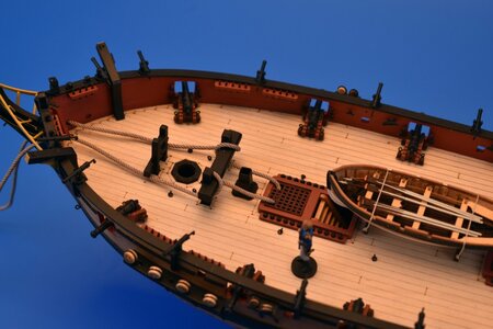
See what I mean? The anchor ropes come through the hawse ports at the deck line, go down through a hatch, and yet somehow they are raised by a capstan at the aft end of the model. The Admiralty drawings show faintly that there is a capstan at the aft end as shown in the kit but that doesn't really explain how the anchor was raised.
What these photos show (of the actual kit) is that the anchor rope would have to have been pulled up from that hatch and then laid down across the deck going aft to the capstan. Nothing about this makes any sense to me at all. I've built a lot of British ships over the years, and I've never seen anything quite like this.
Bob Hunt
I know from 34 years of building model ships experience that this just doesn't seem correct. To raise the anchors, the cable would have to be strung across the length of the deck aft to the capstan. I know from building the Royal Caroline that it used two pulleys, one on each side of the deck at the bow where smaller ropes were strung which were tied to the anchor cable and led aft to the capstan which was in the middle of the deck. These ropes wrapped around the capstan so that they were what was actually used to raise the anchor. As the anchor rope approached the capstan, the ropes that were tied to the thinner rope which were tied to the anchor rope were untied and moved.
In other words, the anchor rope itself was not wrapped around the capstan. On the HMS Speedy, photos I've seen show the anchor rope going down a hatch just aft of the fore mast. So how in the heck did they operate the capstan to raise the anchor. None of this makes any sense to me whatsoever.
I know the Admiralty drawing faintly shows the capstan at the aft end of the main deck, but I just can't imagine how they would use it to raise the anchor. In my opinion, logic tells me that there would have been a windlass just aft of the fore mast used to raise the anchor and the anchor rope would then go down the hatch which would have been just aft of the windlass. Does anyone have any historical information on how the Speedy's anchor would have been operated?
I'm planning on building this kit and writing a practicum on it and this anchor thing really perplexes me.


See what I mean? The anchor ropes come through the hawse ports at the deck line, go down through a hatch, and yet somehow they are raised by a capstan at the aft end of the model. The Admiralty drawings show faintly that there is a capstan at the aft end as shown in the kit but that doesn't really explain how the anchor was raised.
What these photos show (of the actual kit) is that the anchor rope would have to have been pulled up from that hatch and then laid down across the deck going aft to the capstan. Nothing about this makes any sense to me at all. I've built a lot of British ships over the years, and I've never seen anything quite like this.
Bob Hunt
Hello, Bob.
While I don't have specific information about 'Speedy', the location of the main capstan in the images above is perfectly fine. Actually, the anchor rope never went around the capstan. The anchor cable was attached to the so-called 'messager' using 'Nippers', this is an endless rope was wrapped around the capstan. Check the drawings from P.Goodwin book
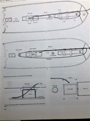
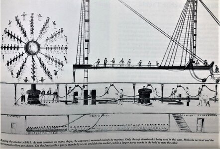
hope this will help.
While I don't have specific information about 'Speedy', the location of the main capstan in the images above is perfectly fine. Actually, the anchor rope never went around the capstan. The anchor cable was attached to the so-called 'messager' using 'Nippers', this is an endless rope was wrapped around the capstan. Check the drawings from P.Goodwin book


hope this will help.
- Joined
- Sep 6, 2017
- Messages
- 290
- Points
- 228

Thanks Jim, I get it now. I knew about the messenger because the Royal Caroline I'm building uses one. Now I understand completely how the rope can enter a hatch at the bow but the messenger can travel to a capstan at the stern. I'll use the method shown in drawing B. Thanks for your help.
Bob
Bob
Maybe this topic can also help in your research about the capstans?
On the NMM you will find also a deck plan showing the capstan at this aft place
Details of Fittings: Capstan, rudder, bitts, catheads, partners, gratings, hatchways, ladders etc.
In this topic we can collect drawings, information and details of all deck fittings Main jeer capstan of HMS Neptune (1797 - 98), a 98-gun Second Rate three-decker Scale 1:24. Plan showing sections and elevations for the main jeer capstan of 'Neptune' (1797), a 98-gun Second Rate...
shipsofscale.com
On the NMM you will find also a deck plan showing the capstan at this aft place
- Joined
- Sep 6, 2017
- Messages
- 290
- Points
- 228

Thanks Uwe. I think I've found enough information on the web now on how the traveler was rigged and other related material such as the nippers and how they were attached.
Bob
Bob
- Joined
- Aug 14, 2018
- Messages
- 587
- Points
- 353

I know this post is a bit late but I just came across it while searching for some information on HMS Speedy. The thing I don't understand is why the hawsers pass down that forward hatch? Surely having come from the seabed they, at best, will be dripping mud and slime but yet are going to be pulled down right on top of the galley! Besides that galley hatch is very close to the fore mast around which, or attached to by a block, the messenger must turn and that would not leave much room for too many nippers to get a good grip on the hawser. I would imagine thy would have be taken further back to the main hatch on a brig like HMS Speedy.
Based on your post I took a closer look at the contemporary drawings and based on my fast check I fully confirm your theory.I know this post is a bit late but I just came across it while searching for some information on HMS Speedy. The thing I don't understand is why the hawsers pass down that forward hatch? Surely having come from the seabed they, at best, will be dripping mud and slime but yet are going to be pulled down right on top of the galley! Besides that galley hatch is very close to the fore mast around which, or attached to by a block, the messenger must turn and that would not leave much room for too many nippers to get a good grip on the hawser. I would imagine thy would have be taken further back to the main hatch on a brig like HMS Speedy.
These are the three drawings available, which can be eaisly checked


First a closer look at the cross section - here I marked the openings and hatches of all decks which are visible and marked as openings in the original drawing
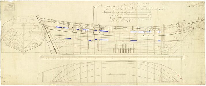
These openings are also visible and match on the deck

and these are the marked openings and hatches down to the hold

So let us now imagine the way where the anchor cable would go
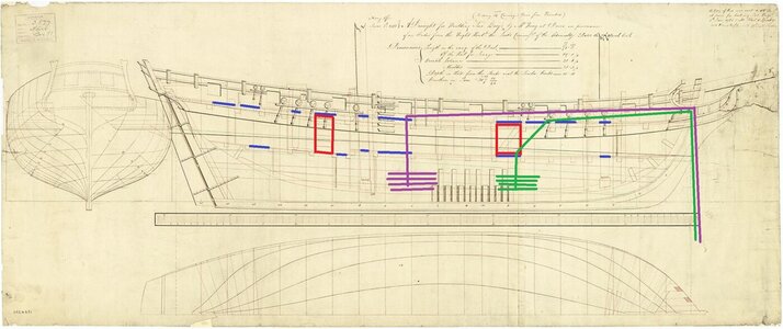
The areas marked in red are the ladder ways - where definitely no anchor cable can pass
The Speedy kit from Vanguard Models has the cable following the green line
But correct would be via the main hatch vertical down to the hold - which is marked in purple
So in my opinion the Vanguard kit is showing this wrong and the cable should go more aft up to the main hatch
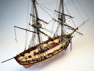
- just my two cents
- Joined
- Aug 14, 2018
- Messages
- 587
- Points
- 353

Good two cents worth Uwe, that looks far much better than the kit version. Guess I'LL have to buy a new front grating,(one with no hawser cut-outs).Thank you for your conformation.

