HMS Triton Build Log

Joined
Apr 8, 2022
Messages
58
Points
78

Location
Beaufort SC
Hello all, I joined about a month ago and mentioned my current project from a William Romero practicum. The HMS Triton. It's a practicum that follows Romero's published practicum of the HMS Warrior. That practicum is 5 volumes. some are hard to get. Fact is that Bill Romero himself got me started on the Triton project. I started communicating with him about 8 years ago. I was interested in his Warrior practicum and wanted volume 2. Went down to see him. He didn't have the book. He twisted my arm to do the Warrior. He gave me CD's and a set of drawings and patterns. The model is scaled at 1/4" or 1:48. So here I am.

Let me start with tools. I mill my own lumber I do it with a Dewalt 8 1/2" circular saw, A Byrnes Saw, and a Preac saw. I have a thicness sander to finish it off.

My materials come from a milling yard where I buy a ten foot piece of raw cherry. I have Mike use his chain saw to cut that log into 4 sections so I can get it in my car. With those pieces I cut each one down to billet stock. The main dimension for the frame patterns is 1 1/4". The other two dims are nominal.

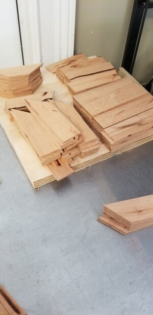
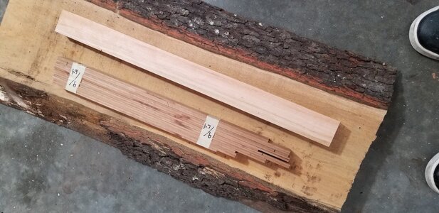
The 106 frames of the Triton are three thickness sizes in the model 1/4, 7/32, 3/16. I will use the Byrnes saw to cut slats 1/8", 7/64", 3/32. I'll cut all of one size at a time to make sure that when I set the first piece to exact thickness all of them will be the same. The photo below shows the three stages of material. 9/64 stock is for a different model.

I'm going to organize some photos so I can proceed.
20220224_102122.jpg
 
Last edited:
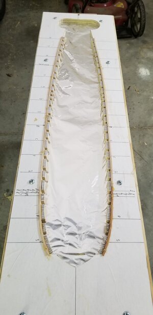
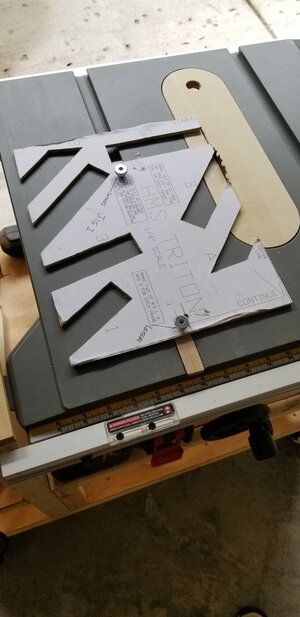
Step 2: build the pattern board. This modelling system goes back to Harold Hahn. You build it upside down. The essence of this system is to take the individual frames "horse shoe shaped and tie the ends to the board. I mentioned earlier that there were three sizes of frames 1/4" being the largest. The pattern board treats these frames differently as they are cut longer to be inserted into notches in the board. See the pattern board below.

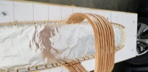
The pattern board is mounted on a crude work stand with casters so I con move it around my garage. The board with the aluminum foil is part of the original practicum suggestion it keeps the glue from sticking to the pattern board. I later decided to cut that aluminum foil board to within 1/2 inch of the edge of the pattern so I could access the inside.
20210520_154045.jpg
 
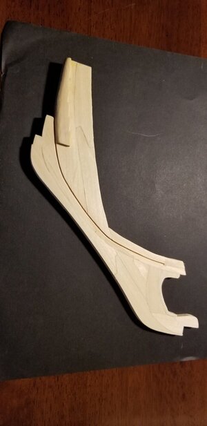
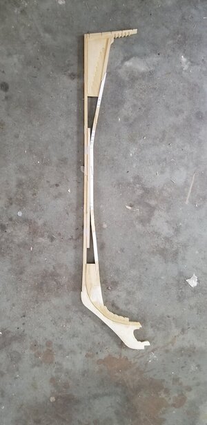
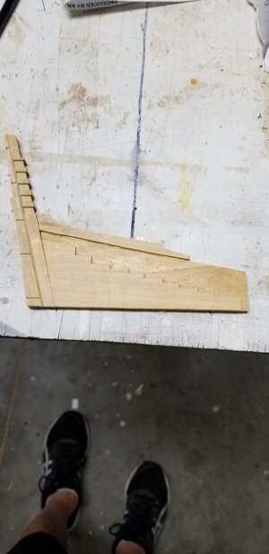
The first assemblies to tackle are the Keel, keelson, stem, stern and stern deadwood. All of these assemblies were pdf files imported into auto cad. I have the student version. The patterns are traced so I could explode them as separate pieces and glue them back together. I used pau marfin wood. It's a light blondish color and extremely hard. You can see the individual piece in the photos. The patterns are cut on a Shop Fox scroll saw. Forgot about that saw.

20210504_172554.jpg20210526_152024.jpg20210520_154016.jpg
 
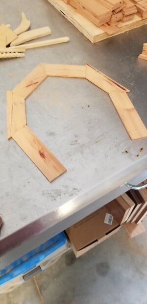
After the keel assembly comes the frame assembly. Each frame is from wood milled to half the frame width. 10 to 11 pieces of milled 1 1/4" wood. Angle cuts using a jig assures the wood is cut precicly. three jigs are used to accomodate hull shape changes.
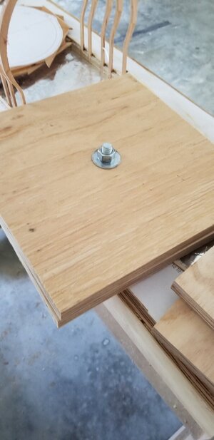
I use the dewaly saw to cut the frame pieces. the pieces are glued using a piece of glass to assure they are flat. when the two halves are dry I glue the two halves together and clamp them using 3/4" plywood and a 3/4" bolt to tighten.
When dry, a pattern is applied to the raw frame stock with rubber cement. Then cut out on the scroll saw. Do that 105 more times. 20210807_104008.jpg20210807_104036.jpg20210807_104045.jpg20210810_171522.jpg20210810_171453.jpg
 
Hi,
which Triton do you want to build? Is it the Mermaid class from 1773 or the 32 gun frigate of 1796?
I am working on a model of the 1773 ship based on my own reconstruction following the the NMM drawings. So I am really interested in your log.
 
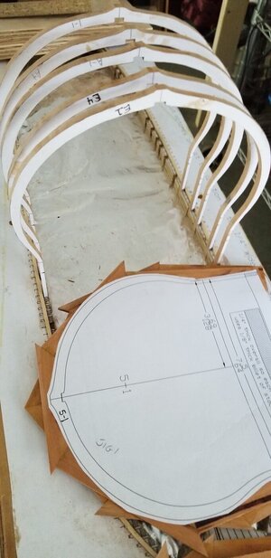
At this point in construction are months of redundancy. So let me go back a bit and talk about the pattern board and frames. As I stated previously the 1/4" frames are the thickest and fit into the notches. I believe that this was set up to manage the distance of frames to each other over the length of the ship. There is also a 1/8" square guide fixed to the framing jig to keep the frames not in notches in line. As a general rule, the 1/4 inch frames are the side boards to each gun port. Each frame is supported and spaced with a 1/16" chock at the keel, at the framing jig and two others I set at the wale and the cut off point. The frames are numbered to match the number and lettering on the "body plan".
I cut all of the straight and bevel frames then dry fit them before I proceded with the gluing. After dry fit I actually took each each body plan letter or number family there were 4 frames in each family. They were faired, glued and clamped together with the chocks. That family of frames was further faired inside and out using an orbital sander. So 4 frame sub-assemblies.
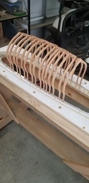
Each of the four frame sections were installed on the construction board and glued and clamped to each other. Also glued to the pattern board. For clamping I had two 3/4" thick plywood squares. 4 holes were drilled in those clamping boards for 1/4" thread rod. As the frames grew the the thread rod allowed me to clamp the whole ship.

Viewed here are 1/4" frames dry fitted into the construction board slots. 1/4" frames are cut longer so they extend down to the foil. Thus serving as anchors. The second photo shows two families dry fit on the board. They will be glued and clamped as 4 frame families, then faired inside and out on the orbital sander. Then glued together. The end result is photo 3. The keel you see is a mock screwed (#6 brass screw in to gage heigth and flatness. That will come off when the real model's keel is placed on the hull. This whole ship will now be further faired with a sander. It's necessary to make this a solid construction to allow the model to withstand the sanding tools vibration. Lots of sanding throughout this modelling process.

So now on to the cant frames. A different animal altogether. The cant frames are cut into two pieces and afixed to the deadwoods.
20211231_131528.jpg20210526_152454.jpg 20210910_101706.jpg
 
Last edited:
A very interesting project - great to see that you started this log - I will follow with big interest
 
Cant Frames
In my previous installment I completed all of the straight and beveled frames. I'll move on to the cant frames. There are 21 aft and 12 fore.

Before the cant frames are attached, the keel assembly with deadwoods, stern post and stem assembly is faired to the completed portion of the hull. I used 4 #6 brass screws to attach the keel assembly to those frames. I created two clamping jigs to assure the keel is perpendicular. Important that the keel assembly does not meander while attaching the cant frames. Not being careful here can cause a bent in the keel or hogging. Hogging happened to me in my first attempt as the keel 's last joint was aft of the last screw. The keel was built in 4 sections using scarf joints. That last joint was a weak point so as I attached my ftames aftward I kept pushing up the keel. I created a 1/8" hogg on a 1/4 scale model. :( I disassembled with a hair dryer. In the future no scarf joints. One continuous keel piece from stem assemble to the stern post. I'll score the joint with a touch from my scroll saw.No one sees the actual scarf anyway.


The techniques for constructing the frames is not different than the straight frames. The difference is how they are attached to the hull. The cant frames are seperated port from starboard and attached to the deadwoods fore and aft. The frames are set into the stern and fore deadwoods.


20210526_152024.jpg20210520_204803[1].jpg20210520_204806[1].jpg20220528_104208[1].jpg20220528_104215[1].jpg
 
Hello all, I joined about a month ago and mentioned my current project from a William Romero practicum. The HMS Triton. It's a practicum that follows Romero's published practicum of the HMS Warrior. That practicum is 5 volumes. some are hard to get. Fact is that Bill Romero himself got me started on the Triton project. I started communicating with him about 8 years ago. I was interested in his Warrior practicum and wanted volume 2. Went down to see him. He didn't have the book. He twisted my arm to do the Warrior. He gave me CD's and a set of drawings and patterns. The model is scaled at 1/4" or 1:48. So here I am.

Let me start with tools. I mill my own lumber I do it with a Dewalt 8 1/2" circular saw, A Byrnes Saw, and a Preac saw. I have a thicness sander to finish it off.

My materials come from a milling yard where I buy a ten foot piece of raw cherry. I have Mike use his chain saw to cut that log into 4 sections so I can get it in my car. With those pieces I cut each one down to billet stock. The main dimension for the frame patterns is 1 1/4". The other two dims are nominal.

The 106 frames of the Triton are three thickness sizes in the model 1/4, 7/32, 3/16. I will use the Byrnes saw to cut slats 1/8", 7/64", 3/32. I'll cut all of one size at a time to make sure that when I set the first piece to exact thickness all of them will be the same. The photo below shows the three stages of material. 9/64 stock is for a different model.

I'm going to organize some photos so I can proceed.
Hallo @T5956ws
we wish you all the BEST and a HAPPY BIRTHDAY
Birthday-Cake
How is your work on the Triton going? Maybe you could show us an update of your work
 
Well all, Its been about a year and a half since I last posted. So I will proceed from there to where I am now. This will include: Hawsers, Stern, Wales, Garboards, Ports, Lower Deck, Main Deck, Cistern Pump, Cannon and their rigging, Hatches. Picture of where I am now. I will probably bore you to tears explaining what I did to get here.

20231010_165951[1].jpg

20231010_165956[1].jpg
 
Before I get into Hawsers I have to admit a construction error. The keel is 4 sections connected by scarph joints. The last joint is about where the cant frames start. During assembly I put pressure on that joint with each frame. Long story short it created a hog about 3/32" starting at the last joint. I had to heat the glue and remove the frames and start over with the cant frames.
20211013_203524-1.jpg


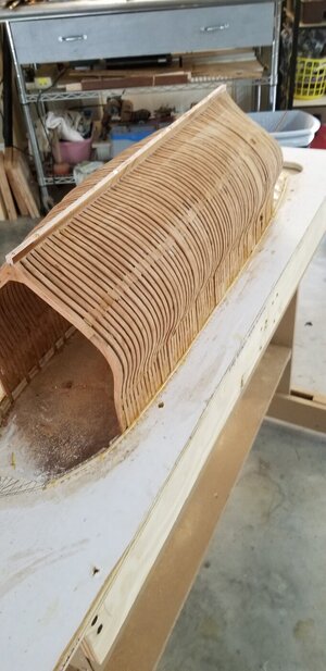
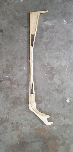
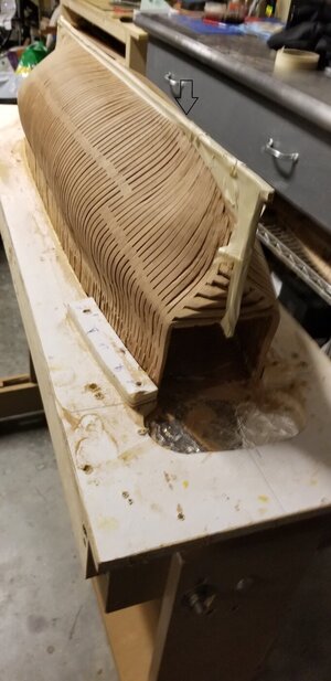
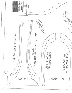
The Hawsers were cut from patterns. Nine per side. Hawser 1 is attached directly to the stem at the rabit. Each of the others are attached without a spacer at the last frame an a 1/16" spacer at the hull line. See photo. Here again I wasn't satisfied with the first pass. Cut them out and started over. After this is all dried say about a full day or two with "Titebond" it's time to fair out the hull. That's several hours of sanding. I used an electric sander with 80 grit paper. Then 120 and finally 220.

Hawser 1.jpg20231010_205402[1].jpg
20211112_131253.jpg
 
Your hull and framing is looking very good - Good, that you were able to correct the damage / error
BTW: Please do not wait so long with the next post - we would all like to follow your work and see photos and descriptions of your work more often
 
Hello all, I joined about a month ago and mentioned my current project from a William Romero practicum. The HMS Triton. It's a practicum that follows Romero's published practicum of the HMS Warrior. That practicum is 5 volumes. some are hard to get. Fact is that Bill Romero himself got me started on the Triton project. I started communicating with him about 8 years ago. I was interested in his Warrior practicum and wanted volume 2. Went down to see him. He didn't have the book. He twisted my arm to do the Warrior. He gave me CD's and a set of drawings and patterns. The model is scaled at 1/4" or 1:48. So here I am.

Let me start with tools. I mill my own lumber I do it with a Dewalt 8 1/2" circular saw, A Byrnes Saw, and a Preac saw. I have a thicness sander to finish it off.

My materials come from a milling yard where I buy a ten foot piece of raw cherry. I have Mike use his chain saw to cut that log into 4 sections so I can get it in my car. With those pieces I cut each one down to billet stock. The main dimension for the frame patterns is 1 1/4". The other two dims are nominal.

The 106 frames of the Triton are three thickness sizes in the model 1/4, 7/32, 3/16. I will use the Byrnes saw to cut slats 1/8", 7/64", 3/32. I'll cut all of one size at a time to make sure that when I set the first piece to exact thickness all of them will be the same. The photo below shows the three stages of material. 9/64 stock is for a different model.

I'm going to organize some photos so I can proceed.
Hallo @T5956ws
we wish you all the BEST and a HAPPY BIRTHDAY
Birthday-Cake
 
So here we ar with all of the frames installed. faired and sanding sealer. On to the garboards and wales. The practicum does not mention the garboards yet in subsequent photos of the project they are shown. I chost three garboards per side using costello boxwood 1/4 x 1/16. I decided on pieces that went the whole length of the ship. As always clamping is an issue. I screwed brackets of wood to the building jig to apply a good angle for bracing. In future planking I moved them around frequently. 20220526_124152.jpg20220526_124321.jpg20220524_143556.jpgOn to the Wales. There are three layers. Two of Costello Boxwood and one of Ebony 1/4 x 1/16 x 8". The positioning was included in the drawings. The base layer is 6 wide, Second layer 4 wide and the third layer, 3 wide is Ebony. Bracing was again an issue. The bow area being the most troublesome. You can see in the last photo I was unsatisfied with the position of one layer I pulled it out and redid it. High heat hair dryers ane great for releasing "titebond" glue
20220423_134154.jpg20220421_171453.jpg
 
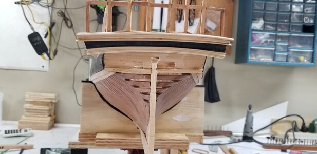
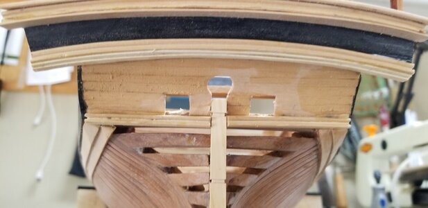
I'll go one more round today. Following the wales I installed the rear framing using cherry stock scroll sawn from patterns. Notice the "wing transom" was pre cut with slots to hold the framing. The second photo shows the coverboards with moldings. Moldings are Costello and Holly woods. The black transom is painted.20220423_134147.jpg20220515_152421.jpg
 
Very good work -> I like your model -> BRAVO
 
A footnote on placing the wales: I started by drawing one line from the pattern on the hull. I took a 1/16 x 1/16 piece of stock and glued it on that line. Taped it down with macking tape. With that glued in place the stock allowed me to position the first line of wale materiaI.
 
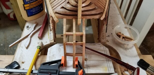
My next segment will include releasing the hull from the build jig. To star with lets finish off the stern knees and the stern coverboards. I did not take many pictures here and frankly what you might see is not the final. I did a lot of rebuilding.
The stern knees were problematic for me as the patterns did not quite meet the models dimensions. 1/8" is a big deal so any variation is an issue. Attaching them to the wing transom notches and still create the proper arc/sweep at the top of the build jig took weeks to master.
Coverboards on the lower part of the stern knees required a compound cut on the scroll saw. I used Costello Boxwood for the piece and the razorblade scrape method to create the molded edge. I could go into this technique deeper but it's basically a box cutter razor blade with the molding's profile ground into it. Scrape the edge of the wood several dozen times to achieve the profile. Pictures below:20220526_124607.jpg20220526_124708.jpg
 
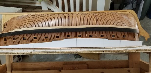
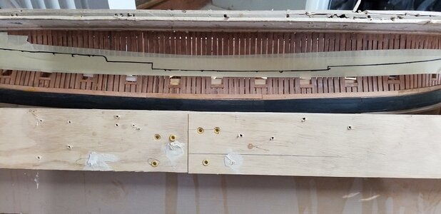
On to the gunport placement and cutting them out. I put much time into being precise. To start, with horizontal placement placement is easy. The sides of the gunports are actually between 1/4" frames. Only 1/4" frame. Placing and lining up the horizontal from stem to stern is critical. There are no true reference points on the hull. Their alignment does not follow the wales. In my picture I took some paper to reference their placement. Scary part of modelling is cutting holes in 8 months of work. 1/16" is a big deal with these. My concern was unfounded because I did actually move a placement or two. The hull is planked from the wale to the toprail outboard and inboard.
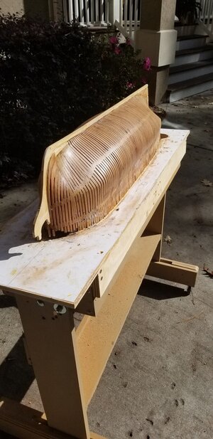
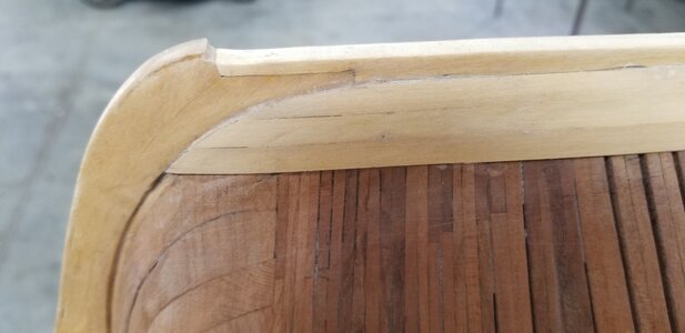
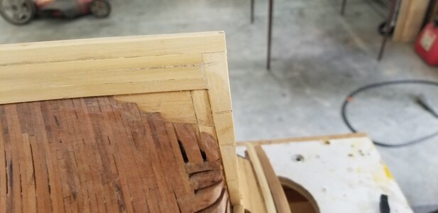
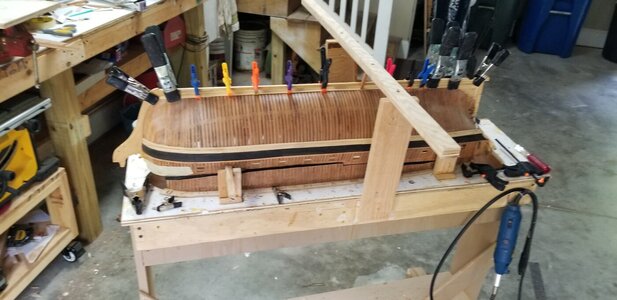
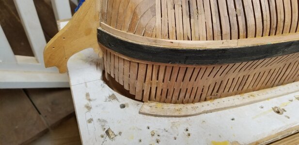
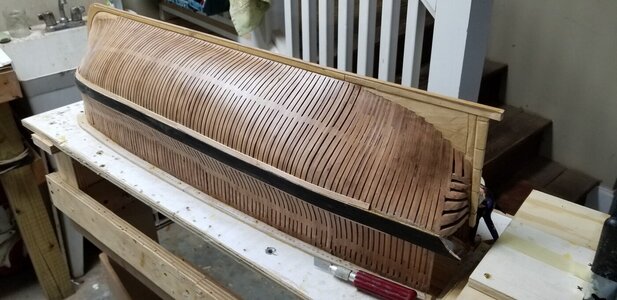
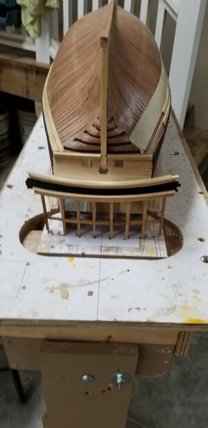
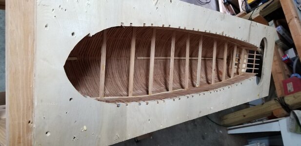
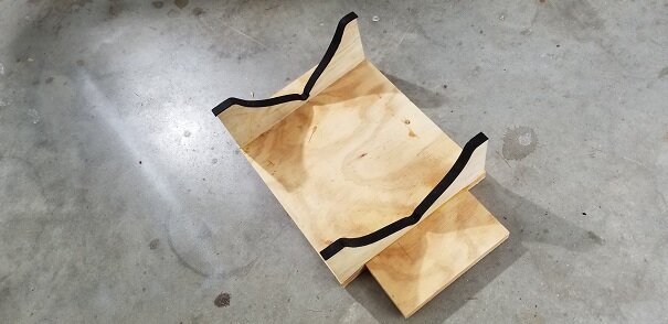
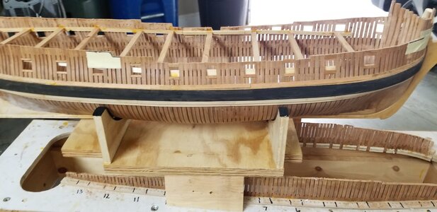
The hull is now ready to part from the build jig. I made a cutout to pattern the cut line. It's seen in the photo. I thought I could produce irrepairable daamage. WRONG!! You can actually refine the toprail pattern/sweep if you make a mistake. Note I added braces. I really did not need so many. See Pics. I'm done for today!20220519_120058.jpg20220521_164722.jpg20220522_104510.jpg20220522_104928.jpg

20220521_164713.jpg
 
Back
Top