- Joined
- Jun 22, 2020
- Messages
- 16
- Points
- 58

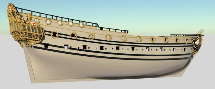
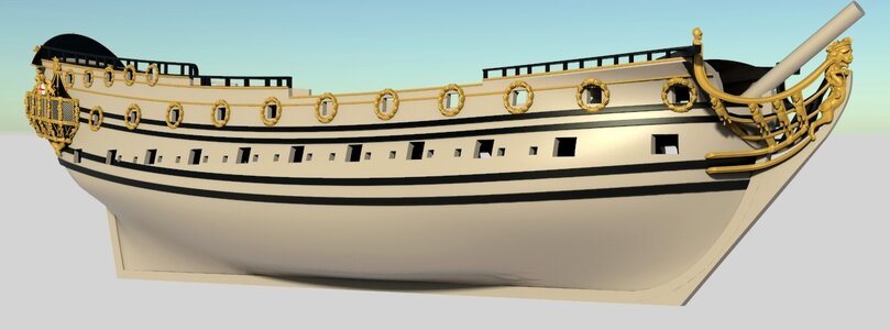
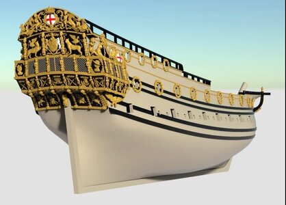
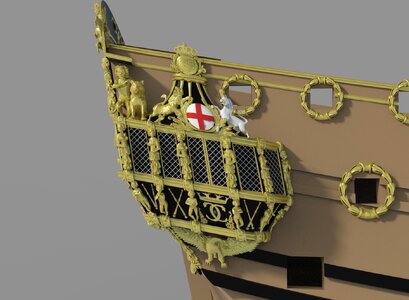
While this is the third scratch built model I have started this is the first time I have attempted to keep a build log - probably because I wanted to fail in private to begin with. Now I am ready to fail in public! My first two models were plank on bulkhead, but this time I will attempt an Admiralty Style model of HMS Tyger (1681), based on the details in the book “The Master Shipwrights Secrets” by Richard Endsor. The model will be in 1:72 scale (as are the drawings in the book), and I want to minimise the amount of painting and aim for a quality wood finish, but much more than this I have not yet decided. This is by far the most ambitious project I have ever attempted and I want to plan it thoroughly. Learning from my last two attempts, I have decided to model everything in Blender first, not just as part of the workflow as I will show, but also to generate my own plans for the detail of how the project will come together. Too often I have found at a late stage that I have misread some detail in the drawings and needed to rework sections - or had to live with the error.
I am also running some experiments to test my planned approach as I have never done this before. I will also share these experiments in case they are useful to anyone.
At the time of writing this first entry I am about 1/3 of the way through modelling the frames in Blender (see screen shot image below). I suspect this is more than half way through by time since I have had several iterations to date as I find the optimum way to manage the topology and as I think through the different stages of the build. I think I now have a satisfactory approach.
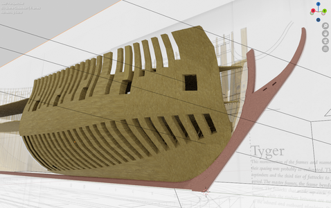
This first screen shot shows progress so far modelling the frames from forward to aft. I first modelled the whole outer hull form from the draught lines in the plans. The topology was subdivided longitudinally at the width of each frame so I could take each frame slice and add thickness and detail as required for each frame. This includes the bevel to test that the thickness of each frame is adequate, although I will only use the broader section (after edge for forward frames, forward edge for after frames) to cut out the frames and then sand the bevel later.
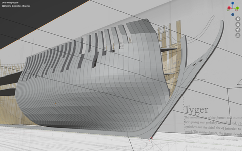
This image shows where I will remove the first futtock above each floor timber to achieve the Admiralty model effect. After researching different styles using Franklin's book "Navy Board Ship Models", I concluded that there was no hard rule but this style seemed contemporaneous for 1681. When I cut the frames I will leave these sections in place at first to help with alignment, structural rigidity and with sanding the bevels. I will remove these sections later before finally gluing all the frames together. Consequently, the "holes" for the missing futtocks are actually just rendered transparent at this stage. The screen shot below shows that the frames are actually modelled whole.
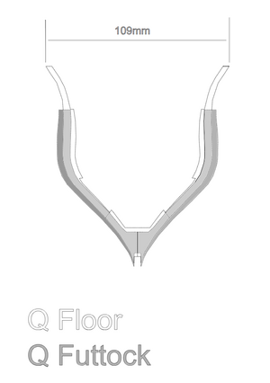
To cut the frames out I am using an Atomstack A10 Pro laser cutter (because I have nowhere near the skill to cut these by hand!). First I export the profile for the frames as an .svg file using the Freestyle add-on for Blender. I edit these in Inkscape to create scale templates for each frame like the one shown below. This will help me check scale, form and alignment as I assemble the wooden frames later.
I then compile batches of frames to fill the size of material billet that I am using, to maximise the use of material and minimise waste. I try to align each piece consistently to the grain of the wood to achieve an authentic grain pattern, as historically the frames had to be cut longitudinally. The example below is for the first frames O through T.
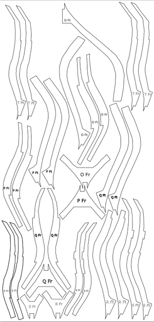
I can then import this image into LaserGrbl to drive the laser cutter. The material I am using is 5mm beechwood, purchased as long planks 15cm wide and cut into 30cm billets. I chose beechwood after an experiment to test different samples using different wood stains. I decided on beach wood with a Shellac stain to get the authentic effect I was seeking. I had a challenge to weed out the pieces with splits and bends (fortunately not many) and reduce the thickness (using a bench planer) as the planks came slightly over size at 5.5mm - even 0.1mm extra makes a big difference over 100 frames. My first learning point was to use the bench top planer in preference to the thicknesser as the latter is not sufficiently accurate and difficult to control.
As I have never done this before, I was keen to take my experiments further, so I used the template for frames O-T to test the laser cutter and check my build process would work. I calibrated the laser using a built in cut test and an off cut from my material. The result in the bottom left corner seemed optimum at one pass on full power at speed 200mm/minute. To reduce scorching it is important to minimise passes while maximising speed and still achieve a cut.
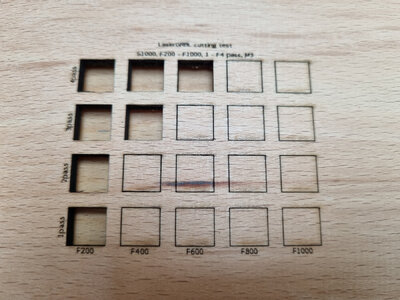
The following image shows the result of the process as I tried this out for real.
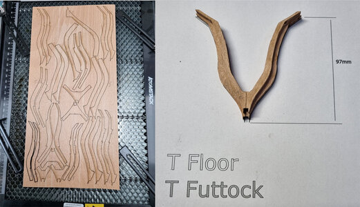
I was generally pleased with the results, but with several learning points:
1. you may notice in the bottom left corner of the billet, the S Floor pieces look darker than the rest. This was because somehow the line thickness in the .svg file was greater than 0pt and the laser tried to literally recreate that with 4 extra passes. This caused a lot of scorching, so I will definitely check that in future.
2. the cut didn't go quite through everywhere. I realised there is some variation in the cutting depth so ideally I need to cut a bit more than I need. I also realised I had not set the speed for the laser in the right way, so it was going a bit too fast. I have now created my own material preset in the LaserGrbl material library with the correct settings.
The image on the right shows the T Frames, with the scorching cleaned off and glued together on the template. This was an important success as it proved the result was to scale, and I could clean the scorching off the frames using a dremmel without destroying the dimensional accuracy.
I will now continue this process of incremental progress and testing. The next step will be to temporarily glue the frames together, sand the bevels, and then separate them to remove the gapped futtocks and cut gunports.
I hope you found this interesting and I would welcome any comments or advice,
regards
Stuart
I am also running some experiments to test my planned approach as I have never done this before. I will also share these experiments in case they are useful to anyone.
At the time of writing this first entry I am about 1/3 of the way through modelling the frames in Blender (see screen shot image below). I suspect this is more than half way through by time since I have had several iterations to date as I find the optimum way to manage the topology and as I think through the different stages of the build. I think I now have a satisfactory approach.

This first screen shot shows progress so far modelling the frames from forward to aft. I first modelled the whole outer hull form from the draught lines in the plans. The topology was subdivided longitudinally at the width of each frame so I could take each frame slice and add thickness and detail as required for each frame. This includes the bevel to test that the thickness of each frame is adequate, although I will only use the broader section (after edge for forward frames, forward edge for after frames) to cut out the frames and then sand the bevel later.
This image shows where I will remove the first futtock above each floor timber to achieve the Admiralty model effect. After researching different styles using Franklin's book "Navy Board Ship Models", I concluded that there was no hard rule but this style seemed contemporaneous for 1681. When I cut the frames I will leave these sections in place at first to help with alignment, structural rigidity and with sanding the bevels. I will remove these sections later before finally gluing all the frames together. Consequently, the "holes" for the missing futtocks are actually just rendered transparent at this stage. The screen shot below shows that the frames are actually modelled whole.

To cut the frames out I am using an Atomstack A10 Pro laser cutter (because I have nowhere near the skill to cut these by hand!). First I export the profile for the frames as an .svg file using the Freestyle add-on for Blender. I edit these in Inkscape to create scale templates for each frame like the one shown below. This will help me check scale, form and alignment as I assemble the wooden frames later.

I then compile batches of frames to fill the size of material billet that I am using, to maximise the use of material and minimise waste. I try to align each piece consistently to the grain of the wood to achieve an authentic grain pattern, as historically the frames had to be cut longitudinally. The example below is for the first frames O through T.

I can then import this image into LaserGrbl to drive the laser cutter. The material I am using is 5mm beechwood, purchased as long planks 15cm wide and cut into 30cm billets. I chose beechwood after an experiment to test different samples using different wood stains. I decided on beach wood with a Shellac stain to get the authentic effect I was seeking. I had a challenge to weed out the pieces with splits and bends (fortunately not many) and reduce the thickness (using a bench planer) as the planks came slightly over size at 5.5mm - even 0.1mm extra makes a big difference over 100 frames. My first learning point was to use the bench top planer in preference to the thicknesser as the latter is not sufficiently accurate and difficult to control.
As I have never done this before, I was keen to take my experiments further, so I used the template for frames O-T to test the laser cutter and check my build process would work. I calibrated the laser using a built in cut test and an off cut from my material. The result in the bottom left corner seemed optimum at one pass on full power at speed 200mm/minute. To reduce scorching it is important to minimise passes while maximising speed and still achieve a cut.

The following image shows the result of the process as I tried this out for real.

I was generally pleased with the results, but with several learning points:
1. you may notice in the bottom left corner of the billet, the S Floor pieces look darker than the rest. This was because somehow the line thickness in the .svg file was greater than 0pt and the laser tried to literally recreate that with 4 extra passes. This caused a lot of scorching, so I will definitely check that in future.
2. the cut didn't go quite through everywhere. I realised there is some variation in the cutting depth so ideally I need to cut a bit more than I need. I also realised I had not set the speed for the laser in the right way, so it was going a bit too fast. I have now created my own material preset in the LaserGrbl material library with the correct settings.
The image on the right shows the T Frames, with the scorching cleaned off and glued together on the template. This was an important success as it proved the result was to scale, and I could clean the scorching off the frames using a dremmel without destroying the dimensional accuracy.
I will now continue this process of incremental progress and testing. The next step will be to temporarily glue the frames together, sand the bevels, and then separate them to remove the gapped futtocks and cut gunports.
I hope you found this interesting and I would welcome any comments or advice,
regards
Stuart


