HMS Vanguard 1787 - Victory Models - 1:72 [COMPLETED BUILD]

So, after sorting out that little lot, on with the jeers.

A little careful investigation showed that lifting off the mast cap wasn’t too much of a problem:

PICT_V_7401
pict_v_7401.jpg

That meant I could make up the pendants for the upper jeer blocks off the model. The diagram shows them to be 0.75 mm but I opted to serve them and so I used 0.5 mm thread. I made off the loop which fits around the mast head first and fitted in place to decide what the overall length should be. They actually ended up about 5 mm longer than I intended but that wasn’t a problem.
Note the 2 mm rings under the blocks:

PICT_V_7402
pict_v_7402.jpg

After a bit of head scratching and experimentation, I decided they should hang inside the main stays. Here they are in place:

PICT_V_7403
pict_v_7403.jpg

Now to see if it all works:
I used a separate spool of thread for each side, starting from the bitts, so I could pull up the two sides evenly together. When I’d threaded them up, the ends were tied to the rings under the blocks:

PICT_V_7404
pict_v_7404.jpg

Here are the other halves of the tackles, on the main yard:

PICT_V_7405
pict_v_7405.jpg

And here’s how the yard looked, ready to be hoisted into place:

PICT_V_7406
pict_v_7406.jpg

After hauling a considerable length of line through the bitts, the main yard is now hanging in its proper position:

PICT_V_7407
pict_v_7407.jpg

I normally like to coil up the actual line rather than make dummy coils but I think I’ll have to cheat in this case. To raise that yard, I pulled 900 mm of line through the bitts. That would be quite a challenge to coil in place.
 
Last edited:
Time to see if I can make a less traumatic job of fitting the fore jeers.

I used the same technique as I’d used on the main jeers to make up the pendants, but these were slightly shorter. I measured the size of the mast top this time rather than trying to size the loop on the actual top. It was just under 7.5 mm square and I reckoned that about a 10 mm diameter would be about right, so I made off the loop around a length of 10 mm dowel. That turned out to be a tight fit, but it did fit!

PICT_V_7501
pict_v_7501.jpg

Rather than try to lace up the blocks under the top as I did for the main jeers, this time I brought the line up through the top and then back down to the yard. That way I could easily thread the line through the blocks:

PICT_V_7502
pict_v_7502.jpg

When both pairs of blocks were threaded, I pulled the upper blocks down through the tops to their correct position and was ready to haul up the fore yard:

PICT_V_7503
pict_v_7503.jpg

Unfortunately, once again, all did no go according to plan! The yard didn’t seem to want to lift evenly.
In order to see what had gone wrong, I pulled the blocks back up through the top and then realised I could lift the pendants off the mast top and drop the whole thing through the mast top to see what was amiss.
(This would have been a much easier way of threading the blocks in the first place!)

PICT_V_7504
pict_v_7504.jpg

#’~%$*^!!

Note that the two lines running off the top of the picture are still threaded through the fore bitts and run on to their spools, so I couldn’t sort things out without cutting one of the lines. At least it was an easy fix, just cut the thread from the starboard block, re-route it and tie it back on.

Having done that, the yard hoisted nicely into place. However I could now see that the sling for the yard was a little longer than I wanted. That wasn’t too much of a problem, I simply cut the three seizings on the looped back section and re-made them with the sling about 5mm shorter.

It’s a bit of a tight squeeze and difficult to see everything under the top, but this is how it all fitted together:

PICT_V_7505
pict_v_7505.jpg

All’s well that ends well!
 
Last edited:
By this time I was on a roll hanging yards and the cross jack should be even easier than the previous two as there are no jeers to fit.
I’d already fitted a sling over the mizzen top and strap and thimble to the yard as per the main and fore yards so it was supposedly just a matter of lacing the two together. Before fitting it, I had a quick look at the plans and found this inset diagram:

PICT_V_7601
pict_v_7602.jpg

This shows a different arrangement with the sling running through a block on the yard. I wasn’t particularly impressed with that arrangement and decided to carry on as planned but I was surprised I hadn’t noticed the block when I built up the yard so I checked the plans.
This is the diagram for the yard from plan 6:

PICT_V_7602
pict_v_7602.jpg

That shows a thimble rather than a block so, for a change, I’m innocent!
What it does show however is a simple line running round the yard and the mast which I had spotted earlier. Rather than simply tying the yard to the mast like this I’d already decided to change this and fit a truss pendant as on my previous model of Astrolabe.
This drawing from Petersson’s book shows the arrangement:

PICT_V_7603
pict_v_7603.jpg

The drawing shows a thimble on the port side of the yard but at this scale I simply seized the line round a 0.8mm drill bit and applied some glue to the thread to hold the shape. I drilled a hole in the port mizzen channel and fitted an additional eyelet for the tackle. The tackle is belayed to the aft hole in the pin rail. I assume that pin is intended for some other line but I’ll cross that bridge when I come to it!
This picture shows the tackle:

PICT_V_7604
pict_v_7604.jpg

Not much to see here but you can just see the truss pendant running round the mast.

PICT_V_7605
pict_v_7605.jpg
 

Attachments

  • pict_v_7601.jpg
    pict_v_7601.jpg
    63.6 KB · Views: 219
Last edited:
The arrangement of the truss pendants on the foremast is a little more complicated, there are actually two of them, together with a nave line to hold them up level with the yard:

PICT_V_7701
pict_v_7701.jpg

Strangely, there seems to be no corresponding arrangement for the main mast.
I’ve hooked the tackles to two of the existing eyelets at the foot of the mast. As these pendants aren’t shown on the rigging plans I assume I’m going to find something else that should be hooked to these later. If so, adding two more eyelets shouldn’t be a problem.
The drawing shows the pendant tackles belayed to cleats either side of the mast. These would interfere with the boarding pikes so I’ve belayed them to the bitts aft of the foremast. I’ve managed to fit five belaying pins in those bitts so things are somewhat crowded. The centre pin is used for the nave line. (I've added an extra block at the rear of the fore top for this.)
The trusses are just about visible in the following two pictures:

PICT_V_7702
pict_v_7702.jpg

PICT_V_7703
pict_v_7703.jpg

Speaking of boarding pikes, I’ve now installed those around the foremast. That’s definitely a job that should have been done earlier but access to the main and mizzen masts is still OK and fitting those will be the next job.
The pikes are photo? etched parts and I can’t say I was impressed with the quality of them. The parts all appear to have been etched from both sides; the problem is that the two sides don’t quite line up. At best this method would give pikes with square shafts but they look like two strips of wood, one on top of the other, but not lined up properly. I spent quite a while filing the first twenty of these into some semblance of a cylindrical shaft. At least they now fit through the holes in the rings around the masts.
Whilst I was filing up the shafts, I also filed up the points. That had a couple of benefits, it made them look better and it also made them sharp enough to stick into a piece of balsa wood as I painted the shafts:

PICT_V_7704
pict_v_7704.jpg

Unfortunately, it also made them sharp enough to sick in my fingers!

After the shafts had dried, I painted the points:

PICT_V_7705
pict_v_7705.jpg

Fitting them wasn’t too bad round the front of the mast but the final ones behind the mast would have been a lot easier without the various tackles in place.
This final picture shows the boarding pikes and the tackles in position:

PICT_V_7706
pict_v_7706.jpg
 
Last edited:
I've just cleaned up another ten boarding pikes. The following picture shows the difference:
p1030928.jpg

The one on the right is as supplied, viewed from the front. From the front or back, they don't look too bad but the one on the left, viewed from the side, shows the problem.
Out of interest, I just timed how long it took to file up the middle one. It took just over 7 1/2 minutes, which doesn't sound too bad = until you remember there are sixty of them. That should equate to 7 1/2 hours but distractions and boredom mean that the job is proceeding in fits and starts!
At least painting them is a quick job.
 
Last edited:
Just a minor update this time.

When I originally checked the parts supplied against the parts list I’d noted that there weren’t enough boarding pikes, but since then I’d forgotten that they’re only fitted around the fore and main mast. When I’d cut out the last twenty from etching sheet 638 I went looking for some more on another sheet thinking there must be more somewhere for the mizzen mast. When I didn’t find them I went back to my parts list and found that it said there should be 50 but only 40 were supplied. I actually needed 42.
I knew there weren’t enough so the reminder that I didn’t need to fit any on the mizzen mast was a minor compensation.
I have some coils of soft and hard drawn brass wire so I cut two lengths of 0.5mm hard drawn wire and filed points on them. That was probably easier than cleaning up the etched parts! When I put them alongside the etched parts they looked slightly slimmer so I gave them a second coat of paint which thickened them up a touch.
Here’s how they look:

PICT_V_7801
pict_v_7801.jpg
 
Last edited:
For a change, the delay between this and the previous entry was in writing up the new entry rather than actually doing the work.

I’ve now completed the truss pendants on all three lower yards, that on the main yard is simply a repeat of that on the fore yard - but this time I managed not to get my lines tangled up.
Again, I drilled the bitts to fit belaying pins. I can probably fit four more if required.

My preference is to fit the yard lifts at this stage so I started with those for the main yard.
The diagram shows the running end (33) leading down the outside of the main top and heading aft. A search to the aft of the belaying plan originally didn’t find it but a more careful look showed it further forward, more or less level with the main mast. That seemed a more logical location but there were still a couple of problems.
First off, the line fairly obviously had to run down through the lubbers hole in the main top. Secondly the plans seemed to show the line made off to a cavel cleat. That’s fine for a line running predominantly fore and aft but doesn’t seem practical for a line running vertically.
So, refer to Petersson’s book once more.
That showed the lifts belayed to the pin rail at more or less the same location as the plan, but it also showed a tackle fitted at this point. The tackle was hooked to an eyelet at the front of the channel.
Yet again, I’m departing from the plans.
There are already three eyebolts in the channels at this point; the forward one is spoken for but I haven’t found anything that attaches to eyelet No.2, so that’s now been claimed.
The arrangement for the fore yard lifts is similar but the eyelet there is already in use, so I added a new one at the front of the channel.
This is how the arrangement looks, the picture is of the fore channel:

PICT_V_7901
pict_v_7901.jpg

There is no pin rail here so the line will be made off to the rail.
The crossjack lifts are as per the plans, there are no tackles on these lines.

As yet, most of these lines are not permanently made off but I have made off the port fore yard lift.
First step is to coil it up:

PICT_V_7902
pict_v_7902.jpg

After adding some dilute PVA, letting it dry, some twisting and adjustment with a couple of pairs of tweezers followed by a couple more wetting and drying sessions, here’s the coil on the rail:

PICT_V_7903
pict_v_7903.jpg

So, how does it look now?

PICT_V_7904
pict_v_7904.jpg

PICT_V_7905
pict_v_7905.jpg

PICT_V_7906
pict_v_7906.jpg

Well at least things line up!
 
Last edited:
Time to do some work on the rigging and fit the topsail yards.

Unfortunately first job was to correct a mistake I made some time ago!
The mizzen topsail halliard is fitted on the port side only but the fore and main topsail halliards are duplicated, one on each side. That means that those two yards should have double blocks in the centre. All three yards had single blocks so the first job was to replace the blocks on the fore and main topsail yards:

PICT_V_8001
pict_v_8001.jpg

Next job was to make up the parrals to hold the yards to the masts. The ribs are photo-etched parts which only needed blackening and the trucks were wooden beads which I stained dark.
The cord is supposed to have eyes at each end which are laced together in front of the yard. Although I seized an eye on the first end, by the time I’d laced up the whole arrangement seizing another eye on the other end wasn’t really an option. Instead I opted to loop the end back through the first eye. The difference isn’t really noticeable.
This is how the fore topsail yard looks:

PICT_V_8002
pict_v_8002.jpg

The rigging of topsail halliards is more or less a repeat of the course lifts but when I checked the requirements for the topsail yard lifts, everything was conspicuous by its absence!
Taking the final component first, the lifts are belayed to shroud cleats which are supplied in the form of castings. Initially I wasn’t particularly impressed with these but on closer inspection I decided I was doing them an injustice and following some work with some small files, they cleaned up quite nicely. They blackened much faster than brass parts using the same solution.
The ones at the top of this picture have been cleaned up, the ones at the bottom are as supplied:

PICT_V_8003
pict_v_8003.jpg

From this point, the lifts run up to a block lashed between the topmast shrouds, effectively half a sister block, then via the block at the end of the yards and up to the topmast cap. I would have expected eyelets at this point but the diagram appears to show them looped around the cap
Lashing the blocks between the shrouds wasn’t a problem and I was able to simply seize a loop on the end of the lift, lift the mast cap off the mast and slip the loop around the cap.
This picture shows that arrangement:

PICT_V_8004
pict_v_8004.jpg

Fitting the shroud cleats looked as though it was going to be a problem but I found a method that worked quite well.
I used a short piece of thread and tied a single overhand knot loosely round the shroud at the required location. Next I applied some PVA glue to the base of the cleat and also to the shroud and then positioned the cleat and left it there with just the glue holding it. I then carefully lifted the loop of thread over the cleat, pulled it tight, brushed off the excess glue and adjusted the position of the cleat.
When the glue had set, I removed the single loop of thread and bound the cleat in place with four turns of thread laid in the grooves on the cleat. I simply tied the ends of this thread as the knot will be hidden by the rope coil.
The thread I used was white 0.1mm line. I think I’m going to use black cotton for the next ones as it doesn’t have to do much and should look a bit neater.
With the cleats in place, I could rig the yards. This is how they look:

PICT_V_8005
pict_v_8005.jpg

PICT_V_8006
pict_v_8006.jpg

At that stage, although the lifts were made off on the cleats, that still left half a dozen trailing ends of line to deal with:

PICT_V_8007
pict_v_8007.jpg

This rather crude looking implement is my attempt to solve this problem:

PICT_V_8008
pict_v_8008.jpg

The two little hooks are for me to coil the line around. The right-hand hook is on the end of a straight piece of wire so I can slide it backwards and forwards to adjust the size of the coil. (It’s tight enough to stay where it’s put.) More importantly, the hooks can be brought together to get the coil off.
This is how it looks with the line coiled around it:

PICT_V_8009
pict_v_8009.jpg

PICT_V_8010
pict_v_8010.jpg

And this is how it looks hooked up onto the cleat:

PICT_V_8011
pict_v_8011.jpg

Only five more to coil up!
 
Last edited:
At this point, I made a start on fitting the spritsail yard. This yard is supported by two pairs of deadeyes slung from eyes in the bowsprit cap. There are four eyes in each side and the bottom ones are the ones the deadeyes attach to – except they were already in use by the lower pair of bowsprit shrouds!
I remember having some problems with these shrouds so I looked back through my build log to see what they were

PICT_V_8101
pict_v_8101.jpg

The additional bowsprit shrouds were made off on the bottom eyelet on the bowsprit cap; they should actually have run to eyelets in the back of the cap immediately behind these (which don’t appear in this picture).
I opted for the simple solution. They’re now sharing the eyelets with the shrouds!

PICT_V_8102
pict_v_8102.jpg

I’ve now mounted all the remaining yards on the ship. These latest additions are the three topgallant yards and the spritsail topsail yard. All four of these are held to the masts (or bowsprit) by sets of parrals so it was back to blackening brew with the parrals ribs.

PICT_V_8103
pict_v_8103.jpg

At the same time, the beads were having a bath in some dark oak stain.
This is one of the sets (the spritsail topsail yard) in place.

PICT_V_8104
pict_v_8104.jpg

I’ve fitted the lifts to all the yards so at least everything looks to be in the right place. However that job didn’t quite go to plan
The plans, sheets 5 7 6, show a pair of single blocks for the lifts on each of the upper mast sections:

PICT_V_8105
pict_v_8105.jpg

Simple enough, so that’s what I fitted way back when. Unfortunately, that arrangement is only applicable to the mizzen mast! On the mizzen mast, the topgallant lifts are made off on the end of the yard, run up to these blocks and then down to shroud cleats. On the fore and main masts, the lifts start at these blocks and then run down to blocks at the ends of the yards.
The option of simply lifting off these blocks wasn’t available as there are now stays made off above them on both the fore and main masts. Just to rub salt into the wounds, there’s nothing above the blocks on the mizzen mast!
Cutting the blocks off and remaking them with an outgoing line was the right way to rectify matters but as the lifts are only 0.1 mm I decided to see if I could cheat. I simply tied a slip knot on the end of the line and looped it around the block. That turned out to be much easier than I expected, possibly because I clean up the blocks with a small burr in the rotary tool before fitting them. That includes the corners where the strop goes round, so the loops didn’t slip off the blocks when I tightened them.
Here’s how the foremast tackles look after a touch up with a black marker pen:

PICT_V_8106
pict_v_8106.jpg

Must stop taking close up pictures, the lines really don’t actually look that fuzzy!

Here’s how the spritsail yards look now:

PICT_V_8107
pict_v_8107.jpg

And here are a couple of pictures showing the current state of play:

PICT_V_8108
pict_v_8108.jpg

PICT_V_8109
pict_v_8109.jpg

Looks like everything is still in line!
 
Last edited:
I’ve now come to a halt in my rigging!

I’m working from Plan 11 on a section titled ‘Rigging Stage 7 – Bowlines’ (no sails).
I’m pretty sure these are actually the buntlines and leech lines, but that’s not the problem. I’ve installed those for the fore course in accordance with the plan, but ground to a halt with those for the main course.

The ones for the fore course run from blocks on the yard, up to blocks under the front of the fore top, backwards under the top to a second set of blocks under the rear of the top and then back down to the timberheads either side of the ships bell.
The diagram for the main course is almost identical, except that there is only a single set of blocks under the front of the main top.
However on closer inspection, the belaying points are shown to be on the rail in front of the main mast. This means that the natural route for the line would take it down in front of the yard (and the main course) but it should run behind it.
Here’s what the plan shows:

PICT_V_8201
pict_v_8201.jpg

The drawing clearly shows the lines (64, 65 & 66) running back in the general direction of the poop deck rail, but that one carries the fire buckets and there’s no provision for making off lines there.
Petersson shows these made off on the rail just behind the main mast but there isn’t room to fit four more pins in there (the buntlines are shown sharing a pin).

Any thoughts anyone?
 
Last edited:
This is Petersson's drawing for the main course:

PICT_V_8301
PICT_V_8301.jpg

The rail that the plan shows them running to - the diagram that Bob's posted above - is the rail you can see in front of the mast.

I think the only option is to run them to the main bitts as per Petersson's diagrams:

PICT_V_8302
PICT_V_8302.jpg

The problem here is that those were fitted with no pin holes. When I later found the need for these, I drilled three leaving as much space between them as possible. There's definitely room for one on at each side, two will be difficult. The biggest problem will be getting in to drill them!

PICT_V_8303
PICT_V_8303.jpg

I've had a very close look at the picture on the box lid (photographed and enlarged) but I can't make out where the lines run to. There appear to be two, possibly three, lines running in the general direction of the main bitts, but I'm not convinced. What I am sure of is that there are no lines heading off in the direction of the poop deck rail!

So, Petersson to the rescue yet again.
 
Last edited:
This latest log entry has almost as many steps backward as it has forward! I’ll start with the progress and cover what went wrong at the end.

The buntlines and leech lines for the fore course are theoretically straightforward but I was expecting threading the lines through the blocks under the fore top to be a bit of a challenge. It turned out to be easier than I expected. The lines are intended to attach to the sails with wooden toggles. If the sails are taken down (or not fitted) the toggles are pulled back to the blocks on the yards. So, with the lines threaded up to the top and then out to the blocks on the yard, I needed some wooden toggles. These really are tiny and I was looking around for suitable pieces of wood when I spotted some brown sleeved telephone wire. Tying the line round this and then snipping it to length worked fine. The hardest job was taking a picture - this is the best I managed:

PICT_V_8401
pict_v_8401.jpg

With the toggles fitted, the lines could be pulled back and the toggles keep them from pulling out of the blocks on the yard.
This is how they look:

PICT_V_8402
pict_v_8402.jpg

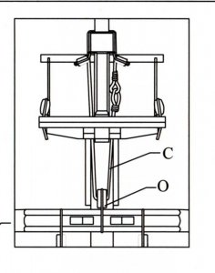
Again not the clearest of pictures but this shows how the lines are routed backwards under the fore top before running down to the timberheads in front of the ship’s boats:

PICT_V_8403
pict_v_8403.jpg

The next picture shows where the lines are made off. Strictly speaking, they shouldn’t be laid on the deck but without the sails, there’s a lot of line to coil up and the coils won’t hang clear of the deck in front of the timberheads. I could hang them over the back but that didn’t look right. I finally decided to leave them there as they would only be like that until the sails were fitted. (That’s my excuse and I’m sticking to it!)

PICT_V_8404
pict_v_8404.jpg

However, looking at the picture, I’ve just realised that the outer coils should have been hung on the rail some time ago!

Time to move on to the main yard. Having abandoned the diagrams on Plan 11 in favour of arrangement shown in Petersson’s diagram, I drilled some more holes in the main bitts (patience - picture coming up later!)
There is only one set of blocks under the main top rather than a set at the front and a set at the rear as under the fore top. That means the lines run down immediately behind the main yard but the arrangement seems fine:

PICT_V_8405
pict_v_8405.jpg

Now this was the challenging part. There are no belaying pins shown in the main bitts but I’d previously drilled three holes and rigged lines to them. In anticipation of possible need for further pins, I’d drilled the outer ones as near to the ends as I could.
This is what it looked like at this point:

PICT_V_8406
pict_v_8406.jpg

Drilling an extra hole each side would be no problem but two each side was risky. There are three lines each side and the diagram shows two bowlines sharing a pin with the leech line on a separate pin. Three lines on one pin didn’t seem an attractive proposition so I decided to try for two each side.
This was the result:

PICT_V_8407
pict_v_8407.jpg

That was a tight squeeze. There isn’t actually enough room between the pins for the lines to drop into the gap. I needed to push them into place with my tweezers!

So what went wrong along the way?

The first thing was that my head-band magnifier got caught under the starboard end of the main yard. The yard survived, but it’s already fully raised so lifting the starboard end meant the port end was going down - despite the lift holding it up. The seizing holding the two blocks to the end of the yard pulled apart.
After removing the old strop, I looped a new length of thread around the yard and then seized a loop round the smaller, lift block leaving a short length of thread through the seizing. I then brought the long end of thread (the length from the reel) up alongside the other two threads and seized round all three creating three loops, one round the lift block, an empty one in the middle and a large one round the yard. I was then able to fit the large block into the middle loop and then pull the large loop tight around the yard. Doing it that way meant that I didn’t have to disturb the rigging of the lifts.
While I was doing this, I noticed something odd. There are two blocks, a large one and a small one, one above the other at the ends of the yards. The lifts on the main yard run (correctly) through the smaller upper blocks but the topsail yard lifts were all run through the lower of the two blocks. As they were rigged after the lifts for the lower yards were correctly rigged, I’m at a loss to explain that one!
That, at first, looked like a major re-rigging job, but as I was slightly shortening the lifts, I decided to try working from top. The lifts are made off around the mast cap. Those yards are in the lowered position so I could raise them to slacken the lifts. I was then able to lift the mast cap and slide the lifts off it. I’d originally formed a noose on the ends of the lifts so once I’d cut the very end of this off, I was able to re-thread the lifts through the correct blocks.
As the lifts were now shorter, that gave me a little bit of spare line to play with but I wanted to keep the tension correct so I replaced the mast cap, wrapped the lift around it and marked the thread where the noose should end. I’d originally seized a small eye around the other leg to form the noose, but in position it was hidden under the mast cap so this time I just tied a couple of half hitches around the other leg. I was then able to lift the mast cap once more and slip the two loops around it.
That wasn’t the last repair job needed. Whilst I was working on the lifts, I noticed that the mizzen topmast stay seemed slack. At first, standing on the starboard side, I couldn’t see anything wrong. On closer inspection, I noticed that the deadeyes and lanyard where the stay attaches to the main mast weren’t in line with the mast. Looking from the port side, the strop around the mast had pulled out of the seizing, but was still in place around the mast.
That required a similar repair to the blocks on the main yard, but it was a little easier as there was only a single deadeye involved.

Mini refit complete!
 
Last edited:
A little more progress on the rigging, I’ve now fitted the main and fore course tacks and cluelines.

This is what the plan shows and the blocks required:

PICT_V_8501
pict_v_8501.jpg

Petersson shows a ‘Tack Knot’ rather than a toggle but because I don’t know how to tie one (and probably couldn’t manage it at this scale even if I did) a toggle it’s going to be.
However, I’ll come back to the inset diagram later.

Three of the lines on each side actually passed around sheaves in the side of the hull and were made off inside. The instructions say to tie a knot on the end of the line and poke it through the slot in the hull. That’s easier said than done, but there’s not much option for the aft-most line. When I finally got it through, a liberal amount of PVA followed it through an on to the knot.
Further forward though, things are a little different, these lines are accessible on the inside:

PICT_V_8502
pict_v_8502.jpg

The cleats for these are actually fitted and whilst they won’t be visible with the ship’s boats in place, they can be used. Starting alongside the eyelet, I threaded the line through a hook, through the rigging, through one of the blocks, back through the rigging and then into the hull. I then pulled a respectable length into the hull and seized an eye on the end.
It was then ‘just’ a case of looping the eye over the cleat and pulling the spare line back out of the hull. ‘just’ is in quotes because the loop wanted to fall off the cleat as I pulled the line out of the hull! Using a stick to hold it in temporarily in place on the cleat solved that little problem. The hook could be seized in place later once the correct position was established.

PICT_V_8503
pict_v_8503.jpg

That accounts for three of the lines, line number four runs via a block on the end of the boomkins. Exactly where the inboard ends of these are fixed isn’t particularly clear,
This is how I’ve fitted mine:

PICT_V_8504
pict_v_8504.jpg

I originally arranged my blocks as per the inset diagram I referred to earlier (picture 8501). That didn’t work particularly well.
If you study the diagram you’ll see that there’s nothing to stop the upper block sliding to the right and down the line marked ‘I’ such that the blocks are separated. The single line, with its toggle, should only pass through the becket of the lower block. That way the blocks are held together.

PICT_V_8505
pict_v_8505.jpg

Here’s how things look now:

PICT_V_8506
pict_v_8506.jpg
 
Last edited:
Continuing on from my last entry, I’ve now fitted the rest of the sheets and cluelines (but not those on the spritsail yards)
Actually installing these wasn’t too much of a challenge, although I had to run a drill through some of the blocks to clean out the holes in them. Making off the various lines was another matter entirely. Somewhat surprisingly, the lines running to belaying pins were the least accessible.
As before, I’ve coiled up the actual line rather than hanging separate coils on the pins or cleats, but I settled for simple coils rather than hanging them with a half-hitch over the pin or cleat.
As before, I used pieces of wire with a hook bent on the end, but this time I just made a simple:

PICT_V_8601
pict_v_8601.jpg

It’s soaked in dilute PVA and hanging out to dry.

I’d previously only used the bits of bent wire on the shroud cleats. This is how I used one to make a coil for the pin rail:

PICT_V_8602
pict_v_8602.jpg

If you’re wondering where the bits of wire and loose ends go, this shows most of them: 

PICT_V_8603
pict_v_8603.jpg

Next job was to persuade the coil on the pin rail that it shouldn’t continue to levitate when I removed the piece of wire:

PICT_V_8604
pict_v_8604.jpg

It had received a dose of PVA earlier so just a cold shower was needed to get it to conform.

This is how things turned out:

PICT_V_8605
pict_v_8605.jpg

After I added this picture I spotted a foreign body apparently hanging from the deadeye you can see between the two coils – so I investigated. It turned out to be the end of the bottom ratline that hadn’t been trimmed off. Needless to say, it’s not there now!

So this is how the rigging looks now:

PICT_V_8606
pict_v_8606.jpg

PICT_V_8607
pict_v_8607.jpg
 
Last edited:
Just a short entry this time, fitting the topgallant yard tyes, another job that got missed somehow. Not only were they not rigged but the holes that represent the sheaves for them weren’t drilled in the fore and main masts. At least that was a simple job.
First step was to seize a loop on the end of the tye. Threading the tye up between the yard and the mast was a tight squeeze but a bit of bent wire pulled it through.
This is the mizzen topgallant yard:

PICT_V_8701
pict_v_8701.jpg

From here the tye runs through a sheave in the mast and down to a tackle.
A really exciting picture here!

PICT_V_8702
pict_v_8702.jpg

The tackle is made off to an eyelet in the mast top, but which one isn’t specified. As the tackles all run down on the port side, I opted for the first eyelet out on that side.
This picture is of the main top:

PICT_V_8703
pict_v_8703.jpg
 
Last edited:
Another stage of the rigging completed; In this case it’s the various bowlines.

This time I was, to put it politely, unimpressed with the plans. The issue was another instance of what both Bob and I experienced with the bow timberheads, multiple lines made off to the same point.
That’s something that’s feasible on the timberheads (just about!) but not on a shroud cleat. This is what plan 9 shows:

PICT_V_8801
pict_v_8801.jpg

Lines 12 and 13 are tricing lines and are only used in an optional configuration of the sheets, tacks and cluelines. Why the port and starboard belaying point for line 12 don’t match escapes me.
Lines 21 and 22 are the topgallant yard ties – which I made off as shown.

The belaying points for the bowlines (without sails) are shown on plan 11:

PICT_V_8802
pict_v_8802.jpg

Six out of eight of these belaying points conflict with those shown on plan 9. Fortunately, I didn’t opt for the optional arrangement on plan 9 so only two lines, 74 and 76 on the port side, the topgallant bowlines, actually conflict.
Rather than finding another home for these, I opted to re-locate lines 21 and 22, the topgallant yard ties.
This is where the lines are now belayed:

PICT_V_8803
pict_v_8803.jpg

Here’s how one of the sets of shroud cleats looks:

PICT_V_8804
pict_v_8804.jpg

And this is how the bowlines look:

PICT_V_8805
pict_v_8805.jpg
 
Last edited:
After a long break in construction. It’s time to get a bit more of the rigging done. This instalment is about the fore and main braces.
In most cases these start from a stay then run to a pendant on the yard and return via blocks on the stay or a shroud to the belaying point.
This picture shows two pairs of blocks on the main stay for the fore course and fore topsail yards:

PICT_V_8901
pict_v_8901.jpg

Nothing like setting off on the wrong foot is there?
The bottom pair of blocks is for the fore course yard and each block is made off to the main preventer stay exactly as shown on a detailed inset drawing on Plan 11.
Although they were a bit fiddly to tie, no problems so far.
At this point I had a look in Petersson’s book (I really should look there ASAP!) and found this nice little detail:

PICT_V_8902
pict_v_8902.jpg
Much easier way to make off the blocks, providing you leave enough line between them to tie the clove hitch. If you check back to the first picture you’ll see that the upper pair are made off this way.
There’s another difference between the two diagrams though, the plan shows the tackle and blocks made off to the preventer stay whilst Petersson shows them on the main stay.
Ah well, that bottom pair are staying where they are so the upper pair are doing likewise.

At this point it’s time for the obligatory backward step:

PICT_V_8903
pict_v_8903.jpg

A block hanging all by itself on a rigging line doesn’t serve any useful purpose. The line is the main course bowline and a little detective work led to the remains of its strop still hooked to an eyelet by the foremast.
This is how it should look, just needs hooking back in place:

PICT_V_8904
pict_v_8904.jpg

So, back to the fore braces. This is how they look rigged:

PICT_V_8905
pict_v_8905.jpg

The fore topgallant braces are made off in the same way as the topsail braces.
There were a number of belaying points missing from the original plans but a pdf file with the additional points marked in red was provided.
The points are for lines 80 to 89 and seem to be all the braces. The first of these, line 80, is the fore topsail yard brace and is made off on the rail by the belfry (the line coming straight down). Line 81, the topgallant brace is also made off on this rail:

PICT_V_8906
pict_v_8906.jpg

The fore course brace is line 79 and I couldn’t find that anywhere on the main plans and it definitely wasn’t one of the new red ones.
I again resorted to Petersson’s book which showed the lines running to the bitts in front of the main mast, However Vanguard doesn’t have any bitts in front of the main mast.
Wrong! It does, but they’re on the deck below, the upper gun deck – and the belaying point is clearly marked on both Plan 11 and the additional belaying points diagram (but not in red). My only excuse is that it’s on its own!

PICT_V_8907
pict_v_8907.jpg

At least I got one thing right, I haven’t yet lashed down the ships boats or I’d never have managed to make off those lines.

Next job was the main course braces. They were the easiest, they run from an eyelet above the stern galleries and back to the pin rail there.
The main topsail braces are similar to those for the fore topsail but the pair of blocks is made off to the mast rather than its stay.
In the case of the topgallant braces, they again run from the stay but the blocks are on the first shroud:

PICT_V_8908
pict_v_8908.jpg

The topsail and topgallant braces are made off to the bitts ahead of the mizzen mast.
Once again I opted to drill the rail and fit belaying pins:

PICT_V_8909
pict_v_8909.jpg

Just for completeness, this picture shows the main brace (the aft pin):

PICT_V_8910
pict_v_8910.jpg

So how does it look now?
Well, like this:

PICT_V_8911
pict_v_8911.jpg

PICT_V_8912
pict_v_8912.jpg

PICT_V_8913
pict_v_8913.jpg

So far I’ve put off fitting the driver boom, but it looks like I’m now going to have to install it – I need it for the mizzen braces!
 
Last edited:
Arthur,
I can wait on that video. I tried making a rope machine that attaches to my ceiling - well, it works with .5mm and larger. Trying to make rope for running rigging won't work. I abandoned it. Seeing your work honestly puts a lot of inspiration back into me that is or was getting lost. Keep going - I don't want to hijack your log with this request.

Donnie
 
Arthur you are a fast builder,you almost finished the Vanguard in four days :text-lol: ,nice yob ,I was following your build on Msb!!
 
It was faster than that!
I started on Thursday and 'almost' finished it on Saturday.

The log has now caught up with the MSB version you've been following and I need to write up a couple more entries of the latest progress - so including the word 'almost' is going to represent rather more than just an extra day! :roll:
 
Back
Top