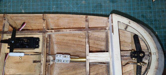
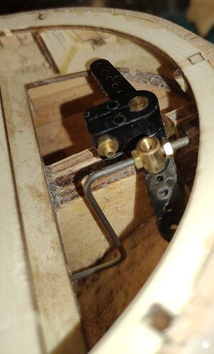
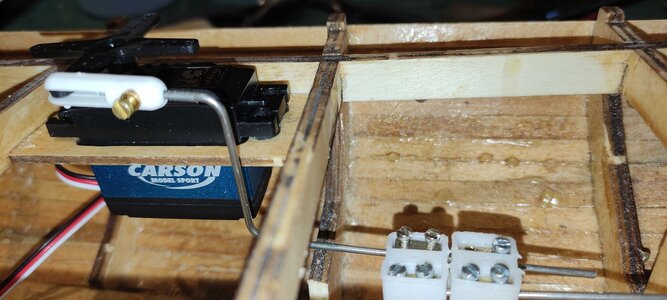
I've just received the RC kit for Occre Ulises and there is a bowden cable supplied to connect the servo to the rudder assembly.
I'm used to fitting bowden cables and adjusters on mountain bikes but this time there are no adjusters.
Would welcome any advice on the best way to fit such a cable on a model board. (At the moment, I've easy access to all the rear bulkheads, etc. as I've delayed gluing the rear deck in place until I know how to solve this problem.
Many thanks.


")