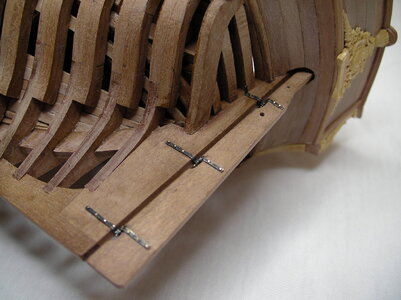
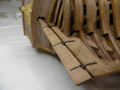
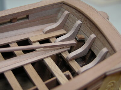
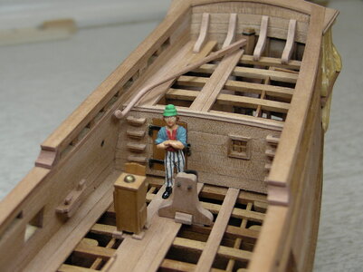
Very nice clean soldering work on these pieces. That is a challenge that you were successful in completing. Rich (PT-2)I spend a few hours on the rudder construction:
View attachment 258576
The supplied parts of the kit.
View attachment 258572
The rudder from the kit is laser cut to the inside dimensions of the drawing and after sanding off the burn marks and beveling at the joint, it is too narrow. So it was remade from scraps from the kit.
View attachment 258574Old and new rudder, the bands and right down from brass own tube with inserted wire. Without tube and wire you can not build hinges and a beginner does not know what to do.
View attachment 258571
New rudder according to the external dimensions of the drawing.
View attachment 258586
Fitting the ruder tiller into the rudder.
View attachment 258589
Rough soldering of the hinges with soft solder on the tapes. The tubes are longer so that no solder can flow into them.
View attachment 258587
View attachment 258588
Top and bottem tubes shortened.
View attachment 258590
On the right, straps for the hull, on the left, straps for the rudder, and at the top, a cuff for the rudder above the tiller.
Best regards
Thomas
You are using an out of date browser. It may not display this or other websites correctly.
You should upgrade or use an alternative browser.
You should upgrade or use an alternative browser.
La Belle - Caf Model 1:48 by Thomas Marocke [COMPLETED BUILD]
- Thread starter Thomas Marocke
- Start date
- Watchers 61
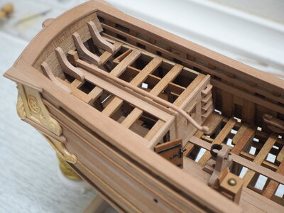
Testplacement of the ruder.
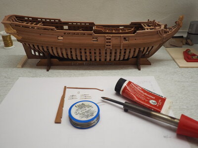
Yes, they are small ruder hinges.
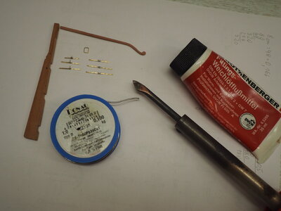
But they were soldered with a normal 40 Watt soldering iron. The components were fixed with pins on a wooden board (no burning fingers) and soldered. The finishing was done with needle files. Somehow the ship model builders are also goldsmiths. With a little practise on waste materials and patience it will succeed. There are so many excellent metal works to see here at "Shipsofscale". Just try and practice! You will get better and better!
Best regards
Thomas
Such a beautiful ship! Great job on the intricate soldering!View attachment 258683
Testplacement of the ruder.
View attachment 258682
Yes, they are small ruder hinges.
View attachment 258681
But they were soldered with a normal 40 Watt soldering iron. The components were fixed with pins on a wooden board (no burning fingers) and soldered. The finishing was done with needle files. Somehow the ship model builders are also goldsmiths. With a little practise on waste materials and patience it will succeed. There are so many excellent metal works to see here at "Shipsofscale". Just try and practice! You will get better and better!
Best regards
Thomas
Thats a beautiful build Thomas.
I spend a few hours on the rudder construction:
View attachment 258576
The supplied parts of the kit.
View attachment 258572
The rudder from the kit is laser cut to the inside dimensions of the drawing and after sanding off the burn marks and beveling at the joint, it is too narrow. So it was remade from scraps from the kit.
View attachment 258574Old and new rudder, the bands and right down from brass own tube with inserted wire. Without tube and wire you can not build hinges and a beginner does not know what to do.
View attachment 258571
New rudder according to the external dimensions of the drawing.
View attachment 258586
Fitting the ruder tiller into the rudder.
View attachment 258589
Rough soldering of the hinges with soft solder on the tapes. The tubes are longer so that no solder can flow into them.
View attachment 258587
View attachment 258588
Top and bottem tubes shortened.
View attachment 258590
On the right, straps for the hull, on the left, straps for the rudder, and at the top, a cuff for the rudder above the tiller.
Best regards
Thomas
Thomas,
What do you mean by 'internal' and 'external' dimensions?
Nice work!
János
In addition to your fine soldering work I really like the shape of the tiller!! Rich (PT-2)View attachment 258683
Testplacement of the ruder.
View attachment 258682
Yes, they are small ruder hinges.
View attachment 258681
But they were soldered with a normal 40 Watt soldering iron. The components were fixed with pins on a wooden board (no burning fingers) and soldered. The finishing was done with needle files. Somehow the ship model builders are also goldsmiths. With a little practise on waste materials and patience it will succeed. There are so many excellent metal works to see here at "Shipsofscale". Just try and practice! You will get better and better!
Best regards
Thomas
Hi Janos!
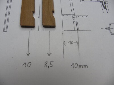
The problem of component size is due to lasering. The laser is guided on the construction lines and thus also cuts out the components too small. The laser should cut outside, that is, in front of the lines and not on them. The right rudder was freed from the carbon and is too narrow.
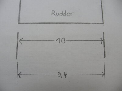
In technical drawings, the lines are part of the component. Nobody draws a component of 10 mm and makes the dimensions outside the 10 mm. In the case of the rudder, it was cut on the lines and building substance is already missing (only 9,4 mm remains). And then the grinding takes place to clean.
An example: If I cut deck planks myself to 5 mm wide and lay them next to each other, I will have 50 mm for 10 pieces. With lasered deck planks, it will happen in most case that after cleaning the planks I will only have a width of 47 mm. An unpleasant event.
Best regards
Thomas

The problem of component size is due to lasering. The laser is guided on the construction lines and thus also cuts out the components too small. The laser should cut outside, that is, in front of the lines and not on them. The right rudder was freed from the carbon and is too narrow.

In technical drawings, the lines are part of the component. Nobody draws a component of 10 mm and makes the dimensions outside the 10 mm. In the case of the rudder, it was cut on the lines and building substance is already missing (only 9,4 mm remains). And then the grinding takes place to clean.
An example: If I cut deck planks myself to 5 mm wide and lay them next to each other, I will have 50 mm for 10 pieces. With lasered deck planks, it will happen in most case that after cleaning the planks I will only have a width of 47 mm. An unpleasant event.
Best regards
Thomas
Last edited:
Thanks for the explanation, Thomas!
Does the laser run on the inside of the line every time or does it depend from which direction the laser arrives at the part? Ie. does the cutter run on the outside edge of the line if the laser 'arrives' from the outside?
János
Does the laser run on the inside of the line every time or does it depend from which direction the laser arrives at the part? Ie. does the cutter run on the outside edge of the line if the laser 'arrives' from the outside?
János
Hi Janos!
Dave Stevens once gave me a nice explanation of these laser errors and how to laser properly.
Can be found at: Kit Reviews: Wood, Plastic, Paper, November 8, 2020, "Basic thoughts about laser cutting".
Best regards
Thomas
Dave Stevens:
I have been creating laser cutting files and working with laser cutters for years.
the laser does indeed have a kerf (width if the beam) the laser i am using now is .012 thousandths so when i finish drawing a part i will offset the lines .012 + .006 for a total of .018 which will take into account the kurf plus a little extra to clean the part. The parts you are showing in post #1 is a poor job of laying out parts.
When you have something like a scarf where 2 parts come together you will be .024 off and parts will not fit right.
looking at this cutting file

when you zoom in close the black line is the keel part the red line is the laser path so the edge of the beam is just shy of the edge of the part

Last edited: Nov 8, 2020
build log of the schooner ALVIN CLARK
http://www.modelshipbuilder.com/e107_plugins/forum/forum_viewtopic.php?19718.post
build log of the ROYAL JAMES
https://shipsofscale.com/sosforums/threads/royal-james-sloop.2450/
3D modeling of a gothic style steam engine 1839
https://shipsofscale.com/sosforums/threads/marine-steam-engines-and-boilers.2272/
Dave Stevens once gave me a nice explanation of these laser errors and how to laser properly.
Can be found at: Kit Reviews: Wood, Plastic, Paper, November 8, 2020, "Basic thoughts about laser cutting".
Best regards
Thomas
Dave Stevens:
I have been creating laser cutting files and working with laser cutters for years.
the laser does indeed have a kerf (width if the beam) the laser i am using now is .012 thousandths so when i finish drawing a part i will offset the lines .012 + .006 for a total of .018 which will take into account the kurf plus a little extra to clean the part. The parts you are showing in post #1 is a poor job of laying out parts.
When you have something like a scarf where 2 parts come together you will be .024 off and parts will not fit right.
looking at this cutting file
when you zoom in close the black line is the keel part the red line is the laser path so the edge of the beam is just shy of the edge of the part
Last edited: Nov 8, 2020
build log of the schooner ALVIN CLARK
http://www.modelshipbuilder.com/e107_plugins/forum/forum_viewtopic.php?19718.post
build log of the ROYAL JAMES
https://shipsofscale.com/sosforums/threads/royal-james-sloop.2450/
3D modeling of a gothic style steam engine 1839
https://shipsofscale.com/sosforums/threads/marine-steam-engines-and-boilers.2272/
Last edited:
This conversation is most informative for me to better understand the dimensional issues. I did have a problem in laying deck planks which were stock and not laser cut, with the carpenters glue was absorbed causing the plank width to expand and those went from a perfect dry fit to not setting down properly causing a finishing issue. Thanks for your information above. Rich (PT-2)Excellent point here. Frames are even more problematic. Two choices: leave the ugly charred line or remove it and lose true shape of the hull. Thanks Thomas for the lovely work and great explanation.
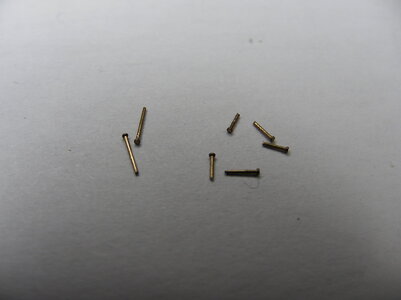
Slowly continues with the rudder. The hinges are mounted with epoxy resin and the tiny nails from Dry-Dock Models & Parts are used. First they were shortened to 2,5 mm. Left original size, right shortened. The nails are very stable and do not bend.
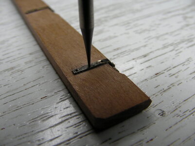
In the already glued hinges the holes were pre-drilled with a 0,3 mm drill.
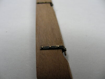
And finally the nails were glued in with resin.
Best regards
Thomas
Wonderful workmanship Thomas, it is a pleasure to follow you log.
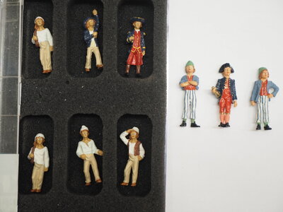
Your rudder fittings are very well done. What is the source of your crewman and the scale? I need to recruit some crew members. Rich (PT-2View attachment 259671
View attachment 259668
View attachment 259670
View attachment 259669
The sailor's arms become heavy when he has hold them up so high on the tiller for a long time.
Best regards
Thomas
Thanks for the likes and comments!

Hi Rich!
The figures are available in different scales. They are made of white metal and still need to be painted. The three right figures are scale 1:44-1:56. They were painted in the colors according to the book "The 74 Gun ship, Vol. 4" by Jean Boudriot.
With the search function: "Figuren" appear the currently available sailors.
Best regards
Thomas
Nice guys Thomas, beautifully painted. It makes any ship more alive.
Yes, a few of those might do for fishermen, not merchant or military naval crew. Thanks, RichThanks for the likes and comments!
View attachment 259705
View attachment 259704
Hi Rich!
The figures are available in different scales. They are made of white metal and still need to be painted. The three right figures are scale 1:44-1:56. They were painted in the colors according to the book "The 74 Gun ship, Vol. 4" by Jean Boudriot.
With the search function: "Figuren" appear the currently available sailors.
Best regards
Thomas
Very good work - good to see, that you also use the small nails for the rudder hinges - on my opinion a very good solution and in scale 

Construction and assembly of the stern lantern.
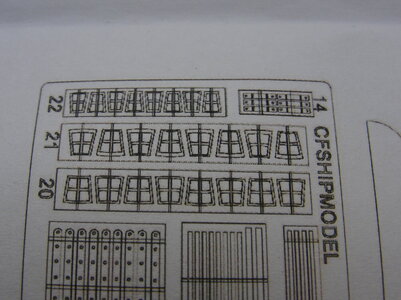
Some individual parts of the lantern according to the construction drawing.
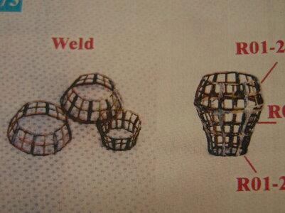
The sequence of the soldering process. Here you must have some practise in soldering, otherwise already soldered components heat up and shift or stick at once completely to the soldering iron.
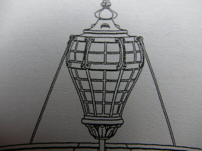
This is how the lantern looks like after the Boudriot drawing.
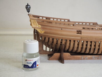
Liquid glass for the glazing.
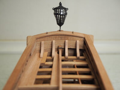
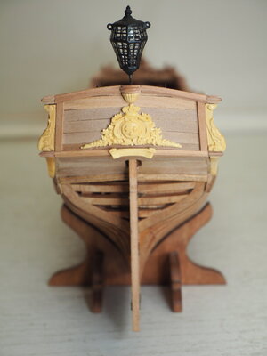
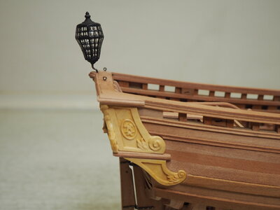
Now the two lateral support struts are missing.
Best regards
Thomas

Some individual parts of the lantern according to the construction drawing.

The sequence of the soldering process. Here you must have some practise in soldering, otherwise already soldered components heat up and shift or stick at once completely to the soldering iron.

This is how the lantern looks like after the Boudriot drawing.

Liquid glass for the glazing.


Now the two lateral support struts are missing.
Best regards
Thomas


