I figured that but the plan I bought only has the drawings and this is my first build and I am making all the parts so it’s quite a task I made my own planking out of ash and walnut on my planet and table sawThe instructions just say to step the mast to the hull. I dont know why you would not glue it in place? You would never keep it in place otherwise.
You are using an out of date browser. It may not display this or other websites correctly.
You should upgrade or use an alternative browser.
You should upgrade or use an alternative browser.
Lady Nelson - Amati 1:64 by Tangopapa - First time PoB Project [COMPLETED BUILD]
Yikes!I figured that but the plan I bought only has the drawings and this is my first build and I am making all the parts so it’s quite a task I made my own planking out of ash and walnut on my planet and table saw
Well, you are resourceful for sure. The first layer in the kit is a more malleable wood, lime wood. The outer skin is walnut. I found on my previous ship, where I stepped the masts, that I wanted to use a glue with longer drying time so that I could fiddle with the masts (3), one at a time, and use the temporary stays and shrouds and angle (rake) template that I made, to get them just right over several minutes, then leave it to dry. The last thing I wanted was to sense the glue setting too soon below the deck, while the mast angles were imperfect.I figured that but the plan I bought only has the drawings and this is my first build and I am making all the parts so it’s quite a task I made my own planking out of ash and walnut on my planet and table saw
Last edited:
Also I need rigging thread is specific for this or is there something I can get at a hardware store as there is no hobby shop in CornwallWell, you are resourceful for sure. The first layer in the kit is a more malleable wood, lime wood. The outer skin is walnut. I found on my previous ship, where I stepped the masts, that I wanted to use a glue with longer drying time so that I could fiddle with the masts (3), one at a time, and use the temporary stays and shrouds and angle (rake) template that I made, to get them just right over several minutes, then leave it to dry. The last thing I wanted was to sense the glue setting soen below the deck, while the mast angles were imperfect.
I had to use some of the rigging from this model for another project and I ordered replacement material from Cornwall Model Boats in the UK. It was fast, accurate and economical.Also I need rigging thread is specific for this or is there something I can get at a hardware store as there is no hobby shop in Cornwall
So far, the Aeropiccola hot bending tool is excellent. You just have to watch where you put it and unplug between planks. It needs a stand like a soldering iron. But it is quick and easy to use.
Bulwark interior planking installed. Just need to sand and trim the upper edge to match the outer planking profile as closely as possible. I think it's going to look good sanded and painted. Next step: cut out the guy ports, sweep ports and other bulwark penetrations on this latest planking. Really enjoyed using the Aeropiccola plank bender. I'm not sure it's the only bender I will use, but it has a place in my toolbox now.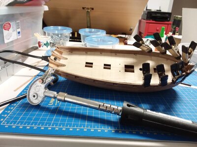

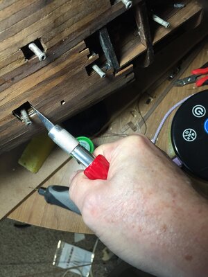
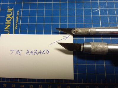
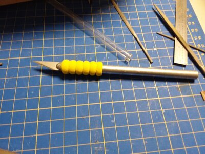
This is the second time holding the knife like a pen, with a new blade that my fingers have worked their way down to the sharp edge. Is it only me or is there a market for a guard or quillion at the end of the Xacto handle? It takes a certain amount of force to cut out gunports...
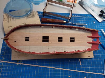
As promised, I trimmed up the edges of the inner and outer bulwark planking and moved on to cutting out the gun ports and sweep ports. That went error free apparently. The next step per the instructions was to install the deck planking. However, I wanted to fill and finish and paint the inner bulwark surface first so that I don't get any paint on my nice holystoned deck planks. So I will plank the deck after interior painting. This meant that I had to paint also the inner edges of the gun and sweep ports. I did not want to get any smudges of red oxide paint on the outer bulwark wood, since it would be hard to remove from bare wood, so I varnished the outside bulwarks but not the hull below them. This is because the main wales have to be glued on there and I want to use white glue, so bare wood to bare wood is best.
However, I couldn't varnish accurately enough to keep it away from the thin line where the upper wales go, so I made, curved, and glued those in place early as well, and trimmed them at the gun ports. I installed them whole, then removed the gunports openings so,they would have a nice fair curve. I just left out the central area where the shroud chains will be fitted. Then they were varnished along with the bulwarks. This also allowed me to paint red the cut ends of the wale where they intersect gunport edges. Looks nice.
Before painting, I varnished all surfaces first as a sealer coat, using Varathane Soft Touch clear, matte finish. This is water based. Any overpainting that comes on this varnished surface, and there was almost none, could be easily lifted immediately with a moist cotton swab. For the red paint, I used some of the artist wife's Ceramcoat by Delta, colour red iron oxide. I dont intend to put a matte varnish over that, I dont see it as necessary, it is a nice, matte finish on it's own.
Now on to plank the deck.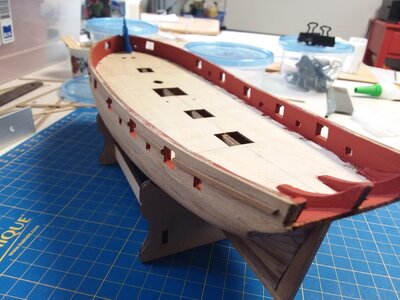
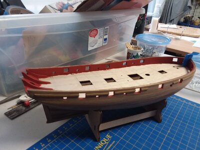


Deck is planked and varnished with matte varnish mentioned above. I was a bit anxious about how exactly to do the outermost planks, which are the only ones that curve continuously along the whole outboard edge, but in the end I just did them as a series of triangles and it worked out fine. The method was obvious when I got to it. I had thought that the forward end of each plank would need to be slightly curved also, but they actually fit best as a series of straight, angled ends.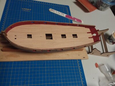

I've put on the stern fascia. It needed some soaking and bending to come into the right shape around the stern counter frames. There are two issues with fit up here.
The first you can't do anything about. I am sure as I can be that the inboard two frames were set in the right position in the slots provided in the false deck. But the ends are flat, perpendicular to the long axis of the boat. I don't think I could have bevelled or faired them to suit the curvature of the fascia. In any case, they needed just a small bit of filler on the inboard edges to close a small gap between them and the fascia. On the two outer counter frames. The fascia is much ,ore curved at that point and I definitely don't think I could have faired the, to the extent needed. I dont think the fascia would have fit in on the necessary line with the top of the stern counter to fit adequately. So some filling was needed there as well. There was a good contact between the frames and the fascia, plenty to glue it well in place, just the angles of the top ends did no allow full surface to surface contact.
At the same time, another issue has to be managed. The stern counter is a flat piece and was already glued in place before the second planking. When the bottom of the fascia was offered up to it, even curved, they had a slightly different shape. The fascia lower edge has to be opened up to a slightly larger radius of curvature and beveled also to come close to fitting. I took it as far as I thought prudent. Too much removed and the fascia becomes to short to meet up with the top of the bulwarks and railings eventually. Its tricky trial and error because you are adjusting a curve in two planes and a bevelled edge all at the same time. I used a dremel sanding drum at slower speed, after carefully marking the new curve line that I wanted.
In the end, I had to fill that small gap too, with some walnut filler. It is fine. Now in the the cap rails. I have prepainted them on top and edges after sealing the wood with varnish and sanding. Once again, I don't want any paint specs on my nice clean deck and bulwarks.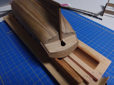
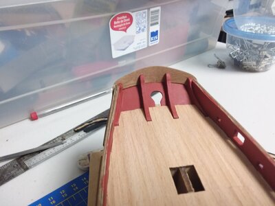
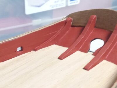


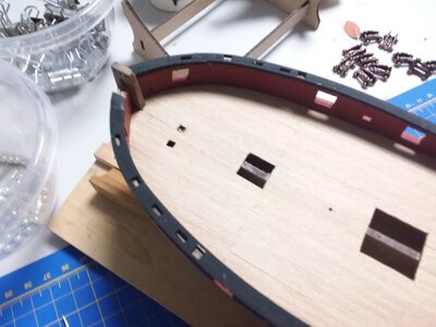
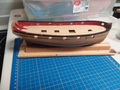
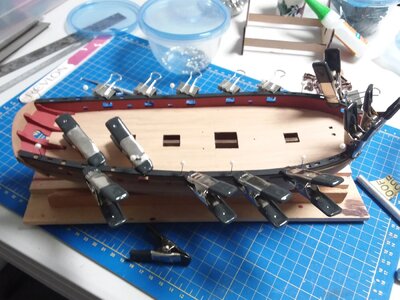
The railing was very tricky. First of all, the curve of the railing doesnt exactly match the circle of the bulwark top as built. So you have to bend the railing the strong way, on edge. The wood grain runs long the long axis of the railing, so it is cross grained up near the bow. It is also very dry and brittle and there are many cutouts in the rail consisting of sharp cornered squares and rectangles. Great stress risers and some leave very, very little meat to take any stress. Or course it broke in three places. It still turned out ok. I wasn't too happy with the inboard/outboard balance of the port railing, so pulled it up at the stern and nudged it over. Tried the same at the bow and it broke at a hole again. I was still able to align everything ok and pin it, but providing vertical clamping force is hard. You can use clamps at every gunport though, where necessary, and even at a sweep port if you can get a small enough clamp.
I would think it would be quite a feat to install this railing without it breaking. Between the extreme loss of material at the cutouts and the grain direction, and the dryness of the wood, the odds are stacked against you. Having said that, it is no great drama to work around that. Fortunately, I didn't use the 10 minute setting carpenter glue, expecting some challenges, and that gave me some response time.
The railing should have been cut at a compromise angle, maybe at 45 degrees to the grain to give better strength overall, but I understand it is less economical in terms of efficient use of the wood. They could have made the railings each in two parts: the more or less straight part along the sides parallel to the grain, and then curved pieces for the rounded bow with the grain at an angle. Yes, you will have a joint to deal with, but a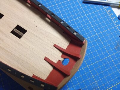
 t least a planned one. With 2 or 3 breaks per side you are dealing with a lot more joints impromptu.
I would think it would be quite a feat to install this railing without it breaking. Between the extreme loss of material at the cutouts and the grain direction, and the dryness of the wood, the odds are stacked against you. Having said that, it is no great drama to work around that. Fortunately, I didn't use the 10 minute setting carpenter glue, expecting some challenges, and that gave me some response time.
The railing should have been cut at a compromise angle, maybe at 45 degrees to the grain to give better strength overall, but I understand it is less economical in terms of efficient use of the wood. They could have made the railings each in two parts: the more or less straight part along the sides parallel to the grain, and then curved pieces for the rounded bow with the grain at an angle. Yes, you will have a joint to deal with, but a


 t least a planned one. With 2 or 3 breaks per side you are dealing with a lot more joints impromptu.
Last edited:
The main wales are now on. Nothing unusual, except somehow I figured the location out wrong and they are 1.5mm too low. I'm not going to take them off, because it is a nice, tidy job otherwise but the waterline will have to be painted correspondingly lower because at midship the main wale is only 2mm above that. After completion, if an observer at my home later notices that the waterline is off by 1.5mm, I will compliment them on their superb knowledge of fictitious cutters. And ask them to leave. LOL.
Now on to the catheads and breasthook, and there is going to have to be customizations there, because there is a design error. Stay tuned.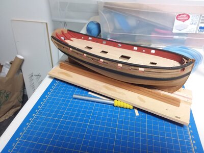
Now on to the catheads and breasthook, and there is going to have to be customizations there, because there is a design error. Stay tuned.

Last edited:
Ok. There are a series of interconnected problems at the bow. Consider the bow gunport as the fixed datum point, because it is there and it is a hole. Yes, it's in the right spot, they were pre-punched in the bulwark plywood. I kind of wonder if that gunport was added in later because there is no cannon supplied for it and I would personally hate to have two open gunports right in the bows letting waves in all the time. Just me. And having it not there would solve a lot of problems. If I built this ship again, I would just plank over it and omit it. Did cutters really have the spare gunport? I can't see them hauling a 3 pounder up to the bow for use as a chaser. I'm curious what people know about that feature on HM cutters. And I think when I have the windlass and bitts in there there won't be room to swing a cat, much less a cannon.
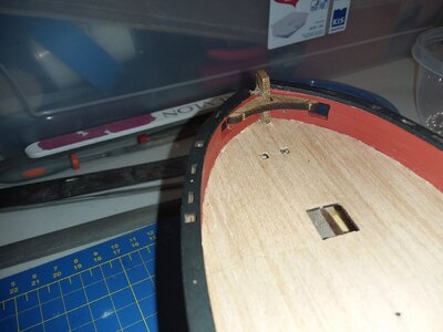
The first problem is that the breasthook is way too big. It covers part of the gunport. The slot in it for the stem is also about 3mm deeper than I needs to be. Now the question is how much smaller to make it because there is another problem.
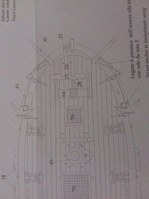
The catheads can't go anywhere near where they are shown on the drawing. And they are shown in at least two different places. First of all, the breasthook takes up the same spot. If I make that smaller, and I will, the catheads still block the gunports. It is like the draftsman saw the conflict and just judged it. It happens. It shouldn't.
In the first picture, you see the problem -- the breasthook fouls the gunport opening. You can slow see how big the stem slot is. You can also just make out slots for timber heads above the gunports, in the railing. The aft edge of the slots and aft edge of the port align.
In the second photo, a plan view from the drawings, you see that the catheads are supposed to be just forward of the timber heads. Which places them right in front of the gunport. Well, at least less seawater will come in there will the cathead half blocking it. And once again, there is no room for the cathead with the breasthook coming back into the gunport.
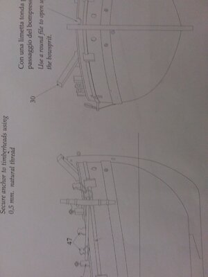
In the 3rd photo, the draftsman accurately shows the upright of the cathead right in the middle of the gunport. Or it is implied -- because that would be a problem, the lines of the cathead are not drawn in although they would be visible through the gunport by mist drawing conventions.
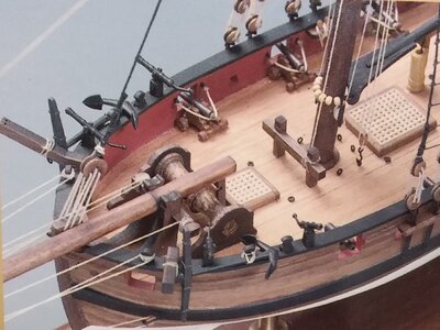
In the 4th photo, from the box art, there is an additional solution-- the cathead has been moved well aft of the timber head and away from the gunport. I think this is what I will do. I was concerned that the catheads would end up to far outboard, and they do crowd the anchor a bit, but the only alternative is to mount them forward of the gunport, and I think that is too close to the bow. It doesn't look right.
Another odd thing is that, looking closely at the catheads in the box photo, the builder didn't sand off the dark laser scorched from the sides affected. Seems like cutting corners in an odd spot.


And I see that DonRobinson said in his build log that he would have planked over those bow gunports also. And I read that, but didn't foresee all the other complications in that tight area. And like him, the windlass is a bit oversized too. I may have to find an aftermarket one. I don't have the ability to reduce the length of the windlass shaft like he did. It is too wide and too high compared to the drawing, but crude cutting will just make a mess.
Last edited:
As my daddy used to say, “A man on a galloping horse thirty feet away would never notice.”


