Lofting in 3D (eg Fusion)

Joined
Jul 18, 2024
Messages
244
Points
213

I'm busy setting up the hull for a new project, an S class destroyer of WW2. I tried several ways to go about to create a smooth flow in the hull and ended up with using the 'station views' and a solid loft. A few questions you may have answers to:

- would you loft the complete hull stern to bow in one go, or would you loft parts (eg stern section, mid section, bow section)
- is the loft actually different when you do the complete vs the section loft? I mean, I cannot really see a difference, but would some line have a different flow?
- does it matter when lofting front to back or back to front?

Note: I will cut the hull in sections at some stage, as otherwise I would not be able to print it (it being almost 5 foot long). But I like to design the thing as a total to ensure all sections really fit smoothly.

Any thoughts?
Screenshot 2024-12-15 at 11.53.40.jpg
 
- would you loft the complete hull stern to bow in one go,

as a CAD designer i would think you are familiar with a "spline" where you draw a line from point to point the edit the line into a smooth flowing shape. I would do the entire hull to create a continuous flow

or would you loft parts (eg stern section, mid section, bow section)
- is the loft actually different when you do the complete vs the section loft? I mean, I cannot really see a difference, but would some line have a different flow?


yes the lines would have a different flow let me work up an example and i will post it


- does it matter when lofting front to back or back to front?

no cad does not know front to back or the other way around it only knows from point to point
 
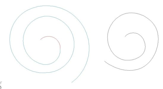
here is what i was talking about
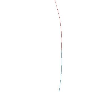
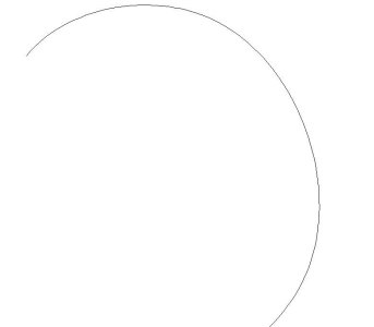
on the left the shape is made in segments to the right is one continuous shape

FLOW1.JPG

looking very close to the left shape you can see the flow is interrupted the line is not a smooth flow from one segment to another

FLOW2.JPG

as one continuous shape it flows

FLOW3.JPG

Fusion is only seeing the start and end point of each section and not the entire flow of a shape
 
I use FreeCAD and the vertices number must match to another for the loft to work. I will aloft in sections, then join sections.....
 
My concern with lofting in sections is that the overall “line” of the complete hull is different from when I loft it as one.

With Dave’s example in mind, I’ll probably make two scaled down versions and print these to see what’s preferable.
 
Hi Marco
I am practicing with FreeCAD on lofting, used in other projects, not ship modeling like to offer help to you. Drawing of a section and will give results in a obj file to you. Ok?

Bill
 
Bill, G'day,

I actually solved the issue, but thanks for offering help.

Fusion is a bit ... awkward ... for hull design. But there is a reason: it makes for perfect craftsmanship iso taking shortcuts.

What I did:
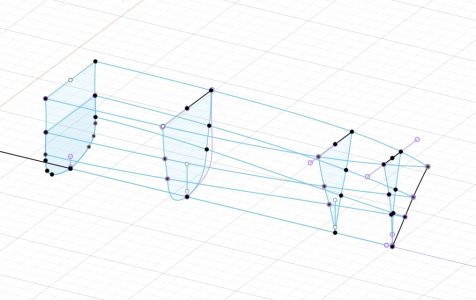
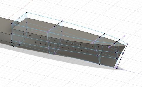
  1. I created a profile view (side view) in three sections, with a keel line as main guide: rear end section, mid section and most of forecastle, and the pointy end of the bow. That way I had independent guidelines for the overall hull and for the up sloping bow (as e.g. the bow will not touch a keel guide for a rear section and so will not let correctly)
  2. I created three plan view levels (top down): one for slightly above the highest dek (to leave some room for a later cut), one for the main deck, extending to the bow line and a third at waterline level, also over the full length. I insured that all three connected exactly with the bow guide line. These would also serve as guide lines.
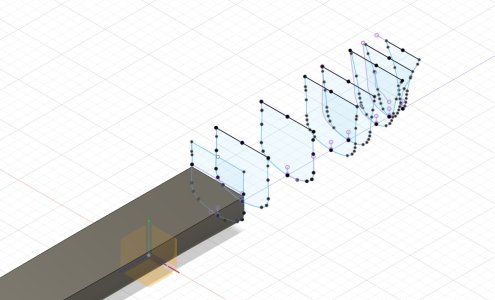
  3. I created the barest minimum of station views (so head / stern on view) - still quite a few - and ensured these connected to the plan view guides precisely
  4. I then lofted the mid section and stern section first. After that I lofted the bow section in two strokes: one for the ribs that still connected to the keel guide and another for the pointy bow end that connected to the bow guide only.
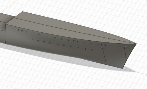
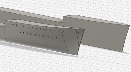
I kept the profile simple, with some material higher than the foreseen decks. After the successful loft I created a cut along the planned deck lines, as you can see in the second image. Thereafter I split the body lengthwise, as I plan to do all the detailing on one side to then mirror to get to a complete hull again.

Next interesting step is the printing ... at 150cm / 60 inches that is going to be interesting. I'm guessing six sections, perhaps seven.

PS: you are not related to the Roguewave Leica photographer, are you?

Cheers,

Marco

Screenshot 2024-12-20 at 10.31.44.jpg

Screenshot 2024-12-20 at 10.32.22.jpg

Screenshot 2024-12-20 at 10.32.58.jpg

Screenshot 2024-12-20 at 10.34.16.jpg
 
Marco, you’ve 99% solved it already. The key is guide rails. If you create single guide rails from prow to stern, it won’t matter if you loft in sections. But if you do sectional guide rails, as you seem to intend, you’ll probably get slight differences from section to section. What I have learned to do when lofting is to try to have the same number of spline points on each section (station) sketch and join each with a guide rail. You will almost certainly still need to fair the rails and sketches later but you will at least have continuity.

When you create guide rails in this scenario, it really doesn’t matter whether you work off a single plane or multiples, because the rails splines are not attached to the sketch plane. I just sketch in whatever view seems easiest.
 
Kevin hi

Really valuable advice! And (perhaps accidentally) I already followed this for the longer stretches. So the guideline for the keel is one piece. The only part where I couldn't work out how to get on was with that bow. I'm sure I will try to get it in one flow, but the up curve and connected mid and top guides are baffling me.

My plan: create a simplified hull and see what the problem is. Thanks for supporting my thinking, really appreciated!

Marco

PS: I am a complete noob at this, having started with Fusion perhaps a year ago. I'm not even a techie :cool:.
 
You’re doing great, Marco. That’s a good plan. The bow and stern need slightly different treatment because you have to have profile sketches perpendicular to the stations and you do need to pre-determine the loft rails. If you create a 3-point or plane at angle for each spline point between the last station and bow sketches, you can sketch the shape of your bow and then fix the loft rail to these. Hopefully that makes sense.
 
That does make sense. And as you can read in the other thread I thought little longer about your advice and just went back in the history line, created continuous guidelines and bingo! Smooth. So thanks! Steep learning curve, enjoying it!
 
Back
Top