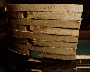
Matthew 1497 1:48 scale by Mike 41 [COMPLETED BUILD]

NOW THIS ONE IS FOR ME I LIKE IT A LOT, AND I LOVE THE TWO GREAT MODELERS WORKING TOGETHER IN TANDUM WITH THIS MARVOLOUS TECH, AS BEFPORE NOT INTERESTED OR UNDERSTANDING THE HOW BUT TO SEE IT WORK IN REAL TIME THIS HAS WHAT I AM LOOKING FOR A TIME PERIOD THAT IS NEW AND IMPORTANT TO THE HOBBY AND A NEW METHOD OF PUTTING IT TOGETHER AND YES DAVE MIKE IS A GEM AND A GENUIS AT DOING THIS THANKS MIKE. GOD BLESS STAY SAFE YOU AND YOURS DON

Thank you Don for the kind words this may be the first partner build but i assure you it is not the last.

there are builders that just want the facts of how to build and the tech stuff is secondary unless you are into the tech and research part of a build.

That was a discussion about the build should we just post a clean simple build like glue part A to part B or should we go deeper into how we arrived at gluing part A to part B.

The Matthew is part of North American maritime history making it more than just another ship model it is a historic ship, built as close as we can to historic methods of ship building.

as i said once before it takes a village to to create a thriving ship modeling community.
 
Thankyou Don for the kind words this may be the first partner build but i assure you it is not the last.

there are builders that just want the facts of how to build and the tech stuff is secondary unless you are into the tech and research part of a build.

That was a discussion about the build should we just post a clean simple build like glue part A to part B, or should we go deeper into how we arrived at gluing part A to part B.

The Matthew is part of North American maritime history making it more than just another ship model it is a historic ship, built as close as we can to historic methods of ship building.

as i said once before it takes a village to create a thriving ship modeling community.

A note from one of the Village People.

Hi Dave, while you fiddle with the blocks post a few pictures along the way. The block assembly method is a fast easy way to build the frames.

I was a lot further along when I discovered an alignment problem went back to my old style out of frustration.

Your posts are very informative with good photos and should be used for the first stage of the build.
 
We should present different approaches to the same build what worked for me may not work for someone else and the other way around.
and exactly what was that "alignment problem"?

When you posted hey dave check the thickness of the frames saved me from building all the frames and then realize i have a problem.
mistakes are the stepping stones to success
 
The alignment problem was my fault, I took this statement literally and did not use a jig to align the frames to the keel or pin the frame parts to the plan

"This is an interesting build because for one thing jigs have become all the rage and the Chinese kits are making more and more elaborate jigs. This build does not use a jig.
the framing has never been done in a kit
it will require some pre-planning
the concept of the build is quite simple to the point you do not even need a set of plans unless you are scratch building. This build "hull assembly" is built by the numbers."

The blocks did not look bad when I glued them to the keel, but the tops of the frames were off a bit, when I tried to straighten them with clamps the frames started breaking and when I removed it from my gantry and threw it on the floor the keel fragmented a little. Problem solved.

I did not feel like this small bump in the road would add any value to the build log, so I omitted it.

Even us saints have a bad day occasionally lol.
 
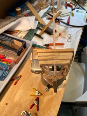
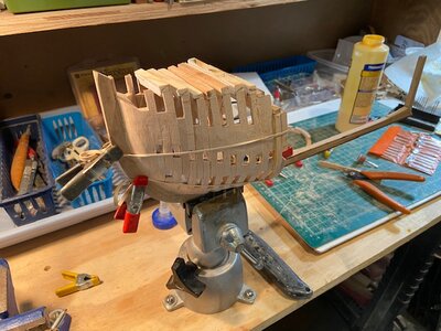
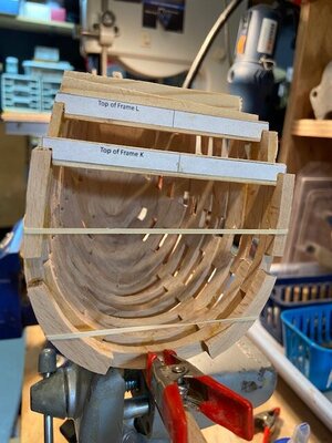
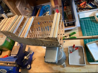
Framing continuation:

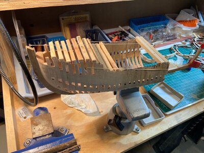
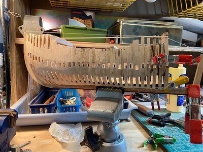
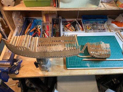
I started adding spacers at the top of the frames and a centerline string from bow to stern to help with the alignment.

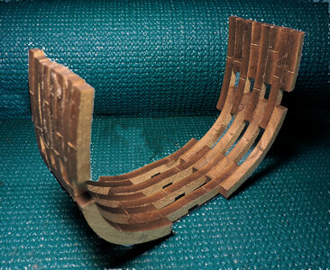
The development of canted frames at the bow and stern of a ship greatly reduces the amount of material and labor in the construction of a ship. This model will give you an appreciation of the advancement.

As I added the new frames to the keel, I matched the interior of the ones installed while there is easy access. I have big hands which is not helpful for this type of work.

This set of progress photos includes one that shows where I was when I started the current build. I use it as a reminder to think before gluing stuff together lol.


IMG_3919.jpgIMG_3926.jpgIMG_3928.jpgIMG_3931.jpgIMG_3932.jpgIMG_3934.jpgIMG_3935.jpg
 
Framing continuation:

I started adding spacers at the top of the frames and a centerline string from bow to stern to help with the alignment.

The development of canted frames at the bow and stern of a ship greatly reduces the amount of material and labor in the construction of a ship. This model will give you an appreciation of the advancement.

As I added the new frames to the keel, I matched the interior of the ones installed while there is easy access. I have big hands which is not helpful for this type of work.

This set of progress photos includes one that shows where I was when I started the current build. I use it as a reminder to think before gluing stuff together lol.


View attachment 316069View attachment 316070View attachment 316071View attachment 316072View attachment 316073View attachment 316074View attachment 316075
Good afternoon, very similar to the Spanish system
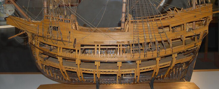
 
Good afternoon, very similar to the Spanish system
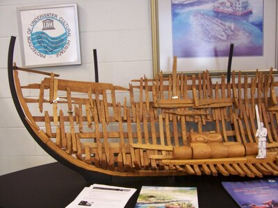
yes your right and one of the primary sources of our research is the San Juan

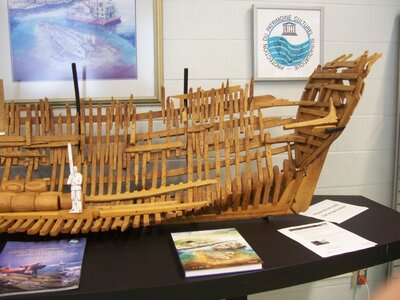
the oldest shipwreck ever found in Canada and one of the most important in the world: a 16th-century Basque whaling galleon that lies at the bottom of Labrador’s Red Bay, a sunken relic from the Age of Discovery that symbolizes the early spread of European civilization — and commerce — to the New World.
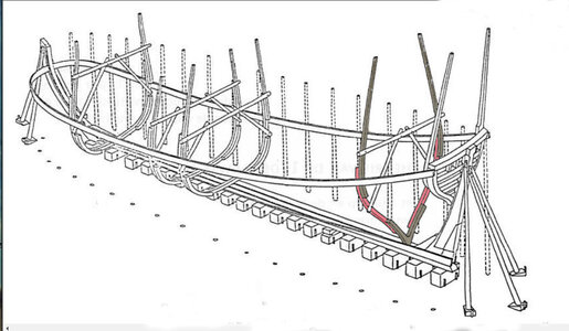
The framing system was known as the shell first where the floor timbers were set in place then the first frame futtock was wedged between the floor heads then planked, then on to the next frame piece and planking.


San-Juan.jpgRedBayShip01.jpgRedBayShip02.jpg
 
Last edited:
"This is an interesting build because for one thing jigs have become all the rage and the Chinese kits are making more and more elaborate jigs. This build does not use a jig.
the framing has never been done in a kit
it will require some pre-planning
the concept of the build is quite simple to the point you do not even need a set of plans unless you are scratch building. This build "hull assembly" is built by the numbers."

an inside joke and Mike refered to me as "the man without a plan" that came from the discussion to offer a set of plans. I thought there are kits offered that do not include plans. So if a detailed build was offered on line a builder should be able to follow the build rather than a set of plans. Well we will see as the project developes.

this project is out of the box thinking and breaks the rules of model ship building. When you buy a kit you get instructions that give you a step by step construction method thought of by the kit designer and how he built the model, same with buying a practicum of how to build a model, these are methods by one person. There is not just one way to build a model we have Mike's build and my build you may take ideas from both styles or hints and tips from other buiders and develope "your" way to build.
Thanks for getting back to me, great job with many hours, if it is permissible on what documentation you are building
 
Thanks for getting back to me, great job with many hours, if it is permissible on what documentation you are building

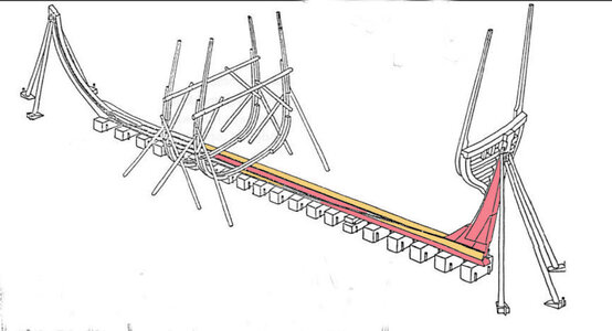
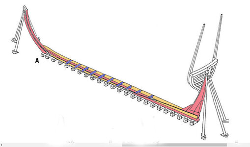
we a happy to share our research into the framing style from illustrations
it is described as laying a keel and adding the floor timbers.
the first plank the garboard is tinted yellow.

hm1.JPG

next the first frame futtocks are added

hm2.JPG

then the bottom of the hull is planked

hm3.JPG
so a hull is built with planking and frame pieces added as the hull is built

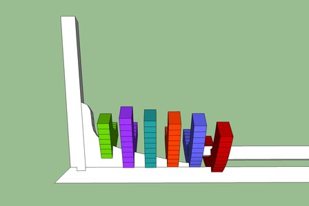
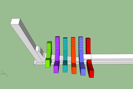
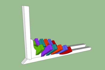
one thing we did notice is the lack of stern deadwood so a little 3D modeling was done to test a method of construction at the stern.

test5.jpgtest6.jpgtest7.jpg
 
Last edited:
as far as what the Matthew looked like we found different replicas and different models. All are basdicly the same type of vessel just differences in the upper works. There are no actual drawings of the Matthew so there is room for interpretation and you have the freedom to build what you want.
matthew england.JPG
MAT LC.jpg
2017-07-26.jpgbristal model.JPG
matthew canada.JPG
 
the main source the model is based on is the drawings of the replica in Newfoundland Canada. However, the replicas are built to modern day standards and are not true to the original construction. That is where we developed our own framing based on historical data of the time period.
 
back to framing

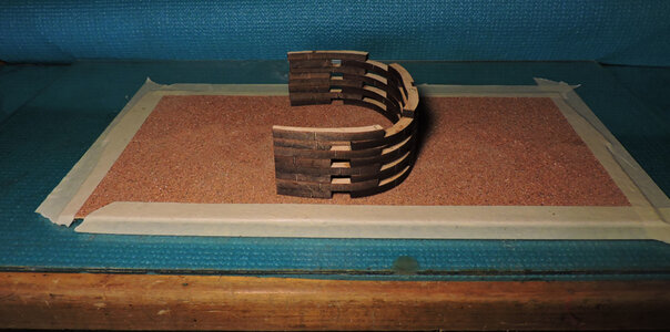
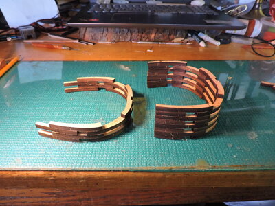
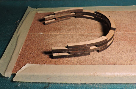
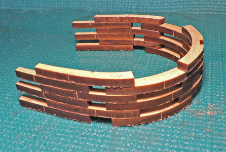
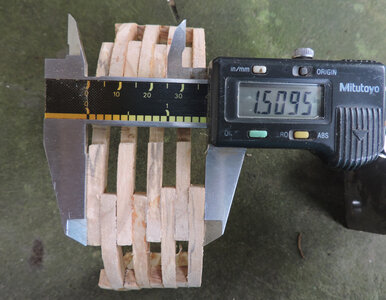
The first block turned out oversize but a little light sanding and it came right down to 1.500. The sanding of the two end frames reduced them by about .020 which make them a little bit thinner. Some one looking a the model would not see the difference until you point it out.

C6.jpg

but i was looking for alternative ways, so i tried this with the next block on the left. I built 2 frames

D3.JPG

i first standed the bottom frame, flipped the frames over and sanded the other frame.

D1.jpg
i can now stack the next frame and give it a light sanding.

D2.jpg

When the final frame in the block is stacked it came out to the perfect size. it would be handy to buy or borrow a set of calipers if you dont have one.
 
And now for something else to go wrong with the build.

"Dave Stevens got it wrong again" a quote from my biggest fan and i mean big really big fan that reads everything i post, steals screen shots of posts, actually analyzing every word., a cyber stalker but that's ok, a little creepy, but still a big fan. So here is a shout out to my cyber stalking fan James Hatch. Don't personally know him or ever had contact but rumor has it he runs the NRG.

so James lets see what i did wrong this time

C1.jpg

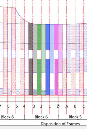
take a look at the first block i built facing the camera it is the midship frame. Now look at Mikes drawing notice anything?
Well let me tell you so you don't make this mistake. In Mikes drawing at the 0 midship the floor is in front of the frame, now look at what i built. Yup the floor is behind the frame.
i actually built the first block backwards.

block 6 a.JPG
 
first i tried to take the block of frames apart but using Gorilla Super Glue that did not work out. It came apart all right but not the way i hoped it would.

e2.JPG
 
Last edited:
fixing the mistake and you all know what they say about mistakes they are the stepping stones to success.

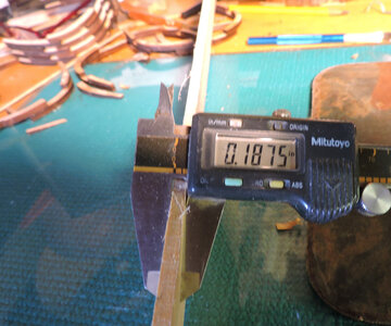
I went out in the shop and cut and sanded a blank sheet the best the machine did was .194 very close but not close enough.
What i did next was get a block of wood and a sheet of sandpaper, just a few passes and i got the sheet to exactly .187

E4.jpg

printed out the frame parts and rubber cemented them to the sheet

E5.jpg
cut them out with a 10 inch table top band saw sanded them to shape with my 6 inch disk/ belt combo sander. Then rebuilt the first block, measured it and it is oh so close it had to actually be the glue joints adding the .009 but no worry it took maybe a minute or two sanding the two end frames.
Now i know how to build the frame blocks and took the rest of the laser sheets ran tape on one side to hold the pieces and hand sanded them down.

E3.jpg

i did notice a difference between building laser cut parts and hand cut parts.
 
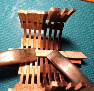
before i go hog wild building frame blocks there is one more thing to check
how will each block fit one another. Mike said when he tried the frames broke apart.

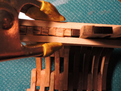
first i clamped the floors of 2 blocks notice the tops of the frames in each block are close.

F1.jpg

the i clamped the top of the frames

F2.jpg
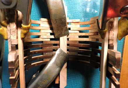
and the other side

F3.jpg
and we have a fit my guess is building and stacking the frames accuratly starting with that key frame by printing out the pattern and pinning the parts as you assemble the frame.

ok it passed the fit test now i can go hog wild and build the rest of the blocks.
 
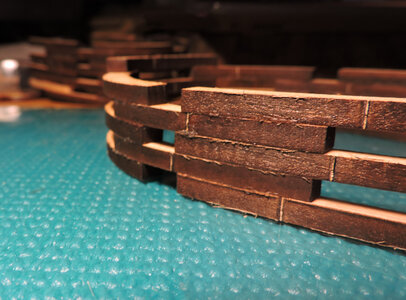
one reason the blocks and frame stack so well is the smooth accuracy of the laser cut

G2.jpg
look at the block i built by cutting out by hand all the frame parts
you looking very close just looking at the block in your hand it looks pretty good. but still there is the introduction of hand cut vs laser cut.

G1.jpg
 
Last edited:
Back
Top