Matthew 1497 1:48 scale by Mike 41 [COMPLETED BUILD]

an up date on frame building

As i build i realized it is important to built the frames as accuratly as you can. Just building and stacking worked fine in the mid section because all the frames were close to the same shape. But as you move forwand and backward the frames change shape from one to the other so just stacking becomes less reliable.

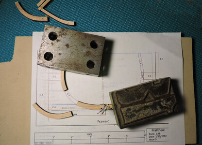
First i pinned the floor to the keel location and used a heavy block to hold the top piece in place.
H4.jpg

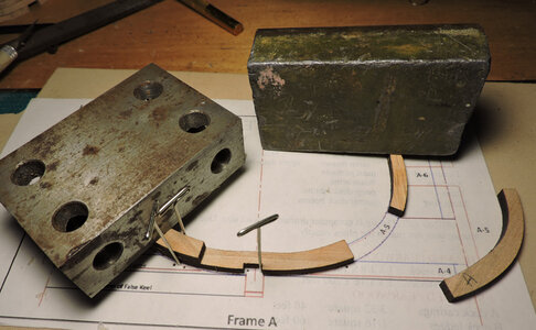
Notice the horizontal lines they are there because you need to place the parts on those lines. If you are to high or low you are changing the arc of the frame.
H3.jpg

take a close look

H2.jpg

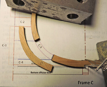
to glue part C3 it has to hit the upper line
H1.jpg
 
Last edited:
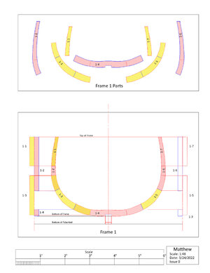
everything you would ever need to know Mike has on each frame drawing


as i was saying try and build the frames as accurate as you can not only do you have to line up the parts side to side but also top to bottom and that is what the lines on the parts and horizonal lines on the plans.

FRAME DRAWING.jpg
 
Last edited:
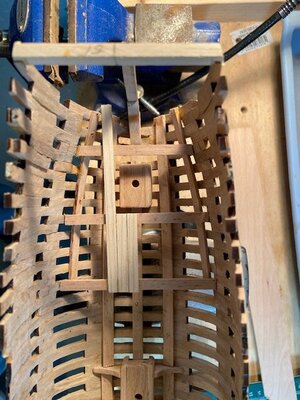
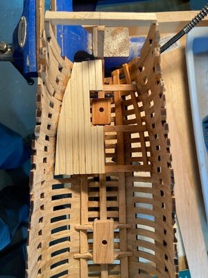
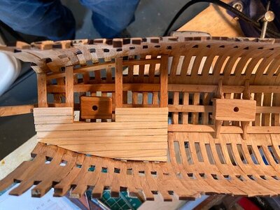
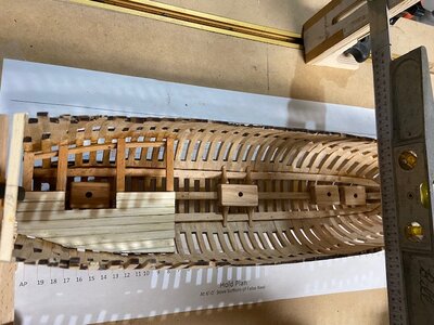
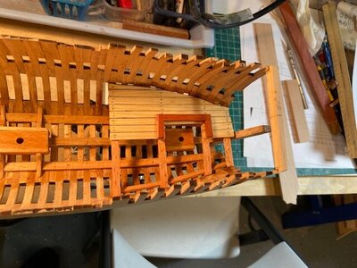
Stern Platform

The small platform located over the mizzen mast step is framed with beechwood the planking is pine and the opening frame is myrtle (a local wood found here).

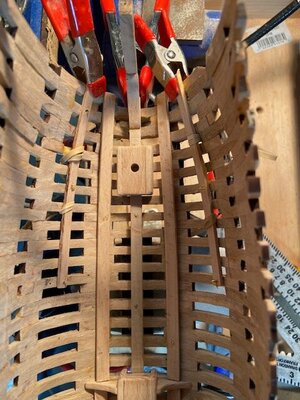
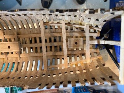
Progress photos.IMG_3953.jpgIMG_3954.jpgIMG_3955.jpgIMG_3956.jpgIMG_3957.jpgIMG_3959.jpgIMG_3962.jpg
 
Bonjour Mike41,
Pour l'instant pas de question, ce forum est un régal par sa diversité et par les constructions de ses membres, vraiment un plaisir pour les yeux et on apprend en même temps beaucoup de chose ! si il y avait une note à donner, ce serait 10/10 :)
@+Christian
 
Bonjour Mike41,
Pour l'instant pas de question, ce forum est un régal par sa diversité et par les constructions de ses membres, vraiment un plaisir pour les yeux et on apprend en même temps beaucoup de chose ! si il y avait une note à donner, ce serait 10/10 :)
@+Christian
Hello Mike41,
For the moment no question, this forum is a treat by its diversity and by the constructions of its members, really a pleasure for the eyes and we learn at the same time a lot of things! if there was a score to give, it would be 10/10 :)
@+Christian
 
Stern Platform

The small platform located over the mizzen mast step is framed with beechwood the planking is pine and the opening frame is myrtle (a local wood found here).

Progress photos.View attachment 316677View attachment 316678View attachment 316679View attachment 316680View attachment 316681View attachment 316682View attachment 316683
Moving right along Mike. She is really shaping up. Such an interesting example of early ship design/building. You and Dave make a great team. It's also a great example of dealing with ambiguity. Finding a way to progress when not having 100% of the information. Really well done.

Thanks for sharing your work.
Ken
Thanks Ken, if the details we have to design ourselves is representative of the correct time period we should be okay.
 
I know you guys know this and therefore, I am taking a risk at mentioning this - as also being a hobby machinist, we all know that two parts that fit together can not be the same exact size. That is a physical impossibility. I can not mill a hole 5mm and expect to have a rod 5mm to fit. Not going to happen. Even if I have a hydraulic press. (well, I guess it could if I had a 60 ton unit, but it would be messy).

So, it seems to me (just for the sake of conversation), that one would have to choose to make the keel notches (like 1/64 larger) to accommodate the real frame size.
Lets say you want the frame to be exactly 3/8" , then the keel notches would have to be 25/64" - that is if you wish to have that much clearance. Or the opposite, the Keel notches can be exactly 3/8" and then the frames can be sanded down to fit or 23/64" (decimal .0.359375).

Maybe I am wrong - just thinking. Therefore, the CAD drawing is probably not taking all of this into consideration.

The designer should provide this type of information with notation on the drawing and references to material lists, procedures etc. if it is required.

If the parts are laser cut removing the char should provide enough clearance at the glue joints. Just my opinion.
 
The designer should provide this type of information with notation on the drawing and references to material lists, procedures etc. if it is required.

If the parts are laser cut removing the char should provide enough clearance at the glue joints. Just my opinion.
Well said, Mike. However, the way laser beam operates (when cutting the wood), makes an angeled cut. It is not just about removing the char, it is more to make a 90-degree side, I think. An extra wood most likely will suffice
 
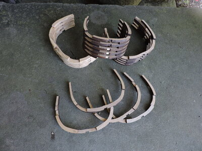
Mike and i had a detailed conversation on laser cutting the parts the amount of material taken out by the laser and fitting pars together.

i do have this topic in the files but did not post anything about it thinking who really cares? But seems someone does care so i can prep up something for the log here.
 
i do have this topic in the files but did not post anything about it thinking who really cares? But seems someone does care so i can prep up something for the log here.
That would be great, Dave. SOS is well known for those types of articles. We like to learn, We are a curious bunch!
 
The drawing CAD or hand drawn is a picture of the finished product as designed. It can be used in many different processes depending on the fabrication method. Dave is well versed in the modern technology; I am just a saw and hammer guy.
 
what is good about this partner build is Mike can keep on building and i can break away with a little "how did they do it" tech talk
so Mike don't mind me just carry on.


However, the way laser beam operates (when cutting the wood), makes an angeled cut. It is not just about removing the char, it is more to make a 90-degree side, I think. An extra wood most likely will suffice

lets start here with lasers cutting on an angle. That is what i call the child fact. Dont get me wrong Jim i am not implying you are a child or making a false or childish statement in part it is true lasers cut on an angle but not all the time and in every case. it is just a general term like when a child will say " but mom you never let me play outside"or "i never ever get what i want" it is a statement generally applied to cover everything,

the angle cut depends on the laser, the operator, the lense and lense setting (focus) Tommy has been cutting for me for 20 years and he knows what i like.


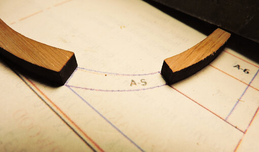
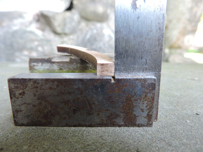
i picked a frame piece at random and took a macro shot of the end as you can see there is no angle to the cut it is square. Ok, as square as needed.


ANGLE.jpg


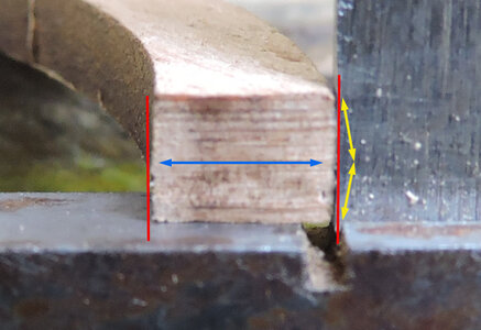
lets look real close and see what is going on. The focus is the depth of the blue arrow, notice the red cuts are square but they have a ever so tiny bow. The yellow arrows are showing an extreme example of the actual cut. It is hour glass shaped.

ANGLE2.jpg
 
Last edited:
. Dave is well versed in the modern technology; I am just a saw and hammer guy.

huh? if this were a shipyard Mike is the master shipwright here, he did the design, did the drawings and created the entire thing from ? plucked out of thin air i guess. i am testing how it will work and how to make it work.
 
Back
Top