Medieval Spanish Coca - AMATI 1:60 [COMPLETED BUILD]

Many thanks, Heinrich!

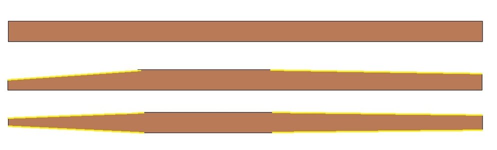
At this point, we need to start shaping the strips. Approximately I removed 2 mm at the bow and 1 mm at the stern, but not symmetrically, because the frames with the largest perimeter are shifted from the centre to the stern. listello sagomato.jpg
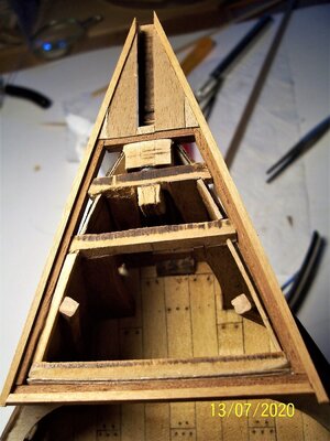
I glued 6/8 strips together and then shaped them at the same time, to maintain uniformity; in the drawing above the shapes used for the strips, testing in place before glueing. The frames are very useful to evaluate the progress of the work:

a1.JPG a2.JPG
a3.JPG 100_0109.JPG

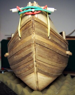
Here you can see that the symmetry has been maintained on both sides:
100_0111.JPG100_0112.JPG

Approaching the keel, the use of stealers becomes essential, as the curvature of the strips becomes unsustainable:b.jpgc.jpg

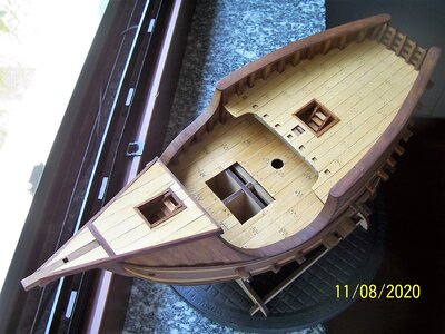
To help the approach of the planking to the keel it is useful to temporarily nail a 4x2 mm batten on the keel, which will be removed at the end of planking: v.jpg

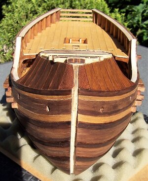
And now the first planking has been completed:

w.jpg x.jpg
y.jpgz.jpg

The next step will be the second planking with the wales.

See you soon!

Rodolfo
 

Attachments

  • listello sagomato.jpg
    listello sagomato.jpg
    33.3 KB · Views: 17
Dear all,
Generally, the second planking is completed with the normal strips and then the wales are glued up to it. We have seen that in this way if particular attention is not paid, it can happen that the planking and the wales have not homogeneous trends.
Actually, the wales are structural reinforcements placed on the skeleton at a much earlier stage, at the stage of setting the hull. The method adopted here will be to place the wales first and next to them the planking courses. For this reason, the protruding part of the beams has been amputated to be re-positioned, rotated according to the inclination of the wales: aa.jpg
First a check about the keel groove:
a.jpg b.jpg

The first wale is located above the upper deck beams (that seems strange...usually a wale is under the beams, but instruction say so) and is a little smaller than the others wales:
d.jpg ab.jpg
Upper the beams there's the normal plank. Under the beams, there's a simple strip; then the spaces between the beams can be covered with pieces of batten.
Now it's time for the first large wale that runs along the entire side of the hull; it is positioned below the beams and in close contact with them: u.jpg At the bow, you should try to bend it as high as possible:

w.jpgx.jpg v.jpgy.jpg
z.jpg

For bending vertically the wales I used an iron at the maximum of power on a soaked strip:
t.jpg
In addition to this, you also have to bend them horizontally to follow the lines of the hull, as with the first planking.

See you soon!

Rodolfo
 
Exactly the same method I use for vertical bending!
 
Right, Heinrich; I think the best thing about the iron is that it has so many different radii of curvature.
Above the wale, I put a clear lime wood strip for the fillings between the beams and above them a normal walnut lath; the cut ends of the beams were re-glued rotated following the slope of the wales: q.jpg r.jpg

I found it very practical to use thumbtacks to fix the laths:

p.jpg o.jpg

I continued upwards with the laying of a couple of normal laths and then a narrower and clearer one before the next wale, which must be as much as possible equidistant and parallel to the previous one. Pliers, rubber bands, clips, everything is needed to make the wale stick:

alfa.jpgbeta.jpg

Given the different slopes, there is a gap left at the stern that needs a shaped strip:
gamma.jpg

this is the result at the end:
omicron.jpg

And here you can see the wale flush with the rail:omega.jpg

In the next post, we'll finish laying the second planking.
See you soon!

Rodolfo
 
On that difficult hull shape it is exquisite planking. :)Thumbs-Up
 
You're right, Heinrich,
although presented as easy for beginners, I actually found it a bit difficult (for myself). Anyway, with patience, we can do (almost) anything!
The following two photos show how the first well-laid planking allows us to continue in perfect symmetry:a.jpg b.jpg
Before moving on to the next wales, it is convenient to put the scuppers, which are not included in the project (inside and outside; unfortunately, I can no longer do the internal ones under the deck, I should have thought of that sooner!):
om1.jpg
om2.jpg om3.jpg

By bending the wales, even with all possible caution, it is possible that being wider and thicker they may break (it happened to me only once, fortunately). The solution is easy and aesthetically valid, as it is also used in real practice: a joint:

sc1.jpgsc2.jpg

See you soon!

Rodolfo
 
I am continued to be fascinated and intrigued by this build. Keep on going!
 
Welcome, mates!
Let's continue with the planking. In this photo you can see how it's possible to adjust (a little!) the laying of the strip more or less at the tip, moving it back and forth.
a.jpg
After three laths we place the last wales:
v.jpgu.jpg
x.jpgy.jpg


Since the plywood bulwarks didn't reach the bow, I made two vertical extensions: w1.jpg
Now you can get to cover the hull with the second planking up to the keel. It's helpful to draw lines to see how the work is progressing:
z.jpg

Unfortunately, I don't have any photos for the laying of the "clinker" planking on the forward bulkheads:
100_0224p.jpg100_0228p.jpg

If I could go back, I would redo the "clinker" with curvilinear strips.

At the end, we apply "oak" colour wood impregnating varnish on the light strips, "Italian walnut" colour wood impregnating varnish on the dark strips and the residue of the bottom of the darker can (richer in pigments) for the joints:

a.jpg b.jpg
c.jpgd.jpge.jpg f.jpg

Now we're going to see about putting in the keel, bow wheel, and stern straight....
See you soon!

Rodolfo
 

Attachments

  • w.jpg
    w.jpg
    263.4 KB · Views: 4
  • g.jpg
    g.jpg
    335 KB · Views: 4
Greetings to all!

Now we've to insert the keel, the bow wheel, and stern straight in the seat that has been left free from planking strips:
a.jpg b.jpg c.jpg

The spur of the bow must be well controlled because the laser cut may not have been perfectly orthogonal:
000_4358p.jpg 000_4359p.jpg

After that, we've to plank both sides of the keel, using walnut strips 1x5 mm:
TRE QUARTI POSTERIORE D.jpgTRE QUARTI ANTERIORE D.jpg

After that, we must plank the upper edges of quarterdeck bulwarks, using 2x10 mm walnut strips, that has been slightly diagonally cut in 30 mm length parts, coupled and applied following the bending: a.jpg b.jpg

As can be seen in previous photos, we've already prepared the rail above the stern board using three strips 3x1 mm.
After that we're going to plank the bulwark edges using pieces of 3x1 mm walnut strips:
c.jpg

Next time, we'll see how to change the bow structure...
See you soon!

Rodolfo
 
Dear all,
At this point, it is also necessary to work on the bow, which has been neglected until now. The manufacturer proposes such a solution, a kind of bow framing:
000_4422.JPG

I have never seen such a structure in any image of the time, among those I have found (Botticelli, 1485):

1485 Botticelli _Judgment of Paris_ - detail.jpg

we will then need to create a frame in the shape of an isosceles triangle:
a.jpgb.jpg
To avoid seeing the thin layer of light-coloured wood on the side of the future deck planking, glue a slim rise (1×1 mm lath) along the perimeter:
d.jpge.jpg

To check the geometric accuracy of the structure, a long square lath (5×5 mm) is inserted and should remain in the centre:

c.jpgf.jpgg.jpg

We begin to plank the surface and build the "frame" for the opening of the bridge in which the ladder will be inserted:

h.jpg i.jpg
The frame is covered with the appropriate strips:
l.jpgm.jpgq.jpg

Since the part underneath is rather unadorned, a traverse was added:

n.jpg o.jpg p.jpg

Next time, we will see the davit.

Dear friends, see you soon!

Rodolfo


Attachments

  • h.jpg
    h.jpg
    240.9 KB · Views: 4
Welcome friends!
Now it is worth thinking about the structure for the movement of the anchors: at that time maybe there were already horizontal winches ("molinete" or "molinello"). But there are many contemporary representations that depict a transom in the bow, straight or curved:
100_0868.JPG100_0867.JPGSta-Ursula-codast-sXV.jpg1470-90 carrack British Museum.jpg
An Italian treatise -1445- -1502- -1495- British Museum 1470-1490

In the Nao of Matarò there is no trace of winches, neither vertical (cabrestante in Spanish, capstan in English), nor horizontal (molinete in Spanish):
100_0866.JPG
From Heinrich Winter - "The Ships of Christopher Columbus"​

Capstan comes from the Latin <<capistrum>> (halter) to which the rope is attached and thus rotation could be excluded. The verb <<capistrare>> with participle <<capistrans-capistrantis>> could have originated the Spanish "cabestrante" from which "cabrestante" by permutation. A hypothesis is that in this case, capstan would be a simple bar, for the times before Columbus.
Anyway, the manufacturer's instructions solve the problem in a somewhat simplistic, not very elegant way:
000_4457.JPG

I preferred to add a bit of work to get something that looked more like the great transom of the Nao of Matarò:

000_4444.JPG

Then the structure must be inserted into the corresponding slots and glued:

000_4458.JPG 000_4459.JPG

000_4461.JPG

Dear friends, see you again soon!

Rodolfo
 
Great work again, I respect your effort in research even that you show us those beautiful historic pictures
 
Thank you, Stephan,
indeed it is difficult to work in an atmosphere of uncertainty, given the lack of documentation of the ships of those times...I've changed Jakob's ladder three times, I still haven't decided where to fix the mainstay, the same for the blocks of the mainmast lifts...

Anyway, now we'll work on the rail above the stern board. Here too the instructions give a reductive interpretation; the Matarò's ship has beautifully shaped strips and supports seem closer:
000_4482.JPG 560223727_mat7.jpg.92cdc47dec43faf95a78e5cd5e4734cd.jpg

Holders have been shaped:
alfa.jpgbeta.jpggamma.jpg

after that, also laths have been shaped:

aaa.jpg ddd.jpg

ccc.jpg

And now we move on to the main deck rail, starting from the top of the aft wall and descending by adding pieces of 1x4x10 mm strips:
uno.jpg due.jpgtre.jpg
cinque.jpgquattro.jpgsei.jpg

zeta.jpg

See you next time!
Rodolfo
 

Attachments

  • zeta.jpg
    zeta.jpg
    284.9 KB · Views: 5
A warm welcome to everyone!
The instructions indicate that the side reinforcements will also be the attachment points for the shrouds, which is why they have a hole in the top:
a.jpg

This arrangement is also plausible since a painting from before 1489 ("Reliquary of St. Ursula" by Hans Memling) shows a similar solution, however with blocks instead of deadeyes. They are also smaller ships than our cocca:
100_0841.jpg 100_0842.jpg
Since, however, the shrouds of this ship will be fixed inside the bulwarks, I provided the construction of the reinforcements as normally structured, without the hole. It is preferable to do a work in series:

b.jpg c.jpg d.jpg

Flaking and cracking are also possible: e.jpg
It is preferable to make a dry test before glueing:
f.jpgg.jpg
If all goes well, the reinforcements are glued and painted:
h.jpg i.jpg

See you soon!

Rodolfo
 
Thanks, Gebirgsmarine!

Dear friends, here we are with the rudder. The original Nao of Matarò has it fixed, glued and with larger hinges and more numerous:
kgEL4A3789.jpg mat11.jpg.1de00751ba5027f15358b7f828aaf765.jpg
AMATI's project has only three shorter hinges:

a.JPG b.JPG
The hinges can also be made of thin cardboard. If you add hinges, you must also prepare hinge housings in the rudder.
In our model, the rudder is constructed by glueing pieces of strips onto an MDF plywood template:
a.jpg b.jpgc.jpg d.jpg

The hinges must be shaped:b000_4576.jpgc000_4617.jpg
f100_0444.JPG g100_0448.jpgm100_0543.jpg

It is advisable to prepare the seat for the little nails: h100_0548.jpg

The final result:

y100_0567.jpg z100_0562.jpg

See you next post!

Rodolfo
 
Welcome friends!
This post is about the quarterdeck rail. As far as this rail is concerned, the manufacturer proposes three simple battens applied on nine columns:
a.jpg
The Nao of Matarò has a more elaborate structure:
cm.jpg
The Matarò ship has a larger number of columns and a certain stylistic refinement. Here a compromise was sought by curving the battens according to the shape of the deck and shaping the columns; indeed it's difficult to add further columns:
b.jpg d.jpg

The strips are a little longer than necessary so that they stay in place by forcing slightly and without glue. In this way the columns are positioned in a controlled manner, glueing them to the deck:
c.jpge.jpgf.jpg
When the columns are glued to the deck, the portions to be glued and the portions to be shaped can be traced on the laths. They can then be shaped:

g.jpg h.jpg

i.jpgl.jpg
In addition, the rail is also completed at the rear:
m.jpgu.jpg

At the top of the columns, I have placed a shaped square:

v.jpgw.jpgx.jpgy.jpgz.jpg

See you soon!

Rodolfo


Back
Top