Medieval Spanish Coca - AMATI 1:60 [COMPLETED BUILD]

A warm welcome to ship modeller friends!
I've forgotten the cargo: it is better to insert it before covering the deck of the quarterdeck
The package contains six barrels with a rather "plastic" appearance. It is advisable to cover them with thin wood strips and reproduce the rims with thin cardboard or coach tape dyed black and glued with vinyl glue:a.jpg

After that, the barrels are tied with ropes to the rings:

b.jpg c.jpg

Have a nice evening!

Rodolfo
 
Dear friends,
the manufacturer suggests a simplified version of the sterncastle:

AA100_0671.JPG WLANL_-_Quistnix!_-_Maritiem_Museum_-_Mataro_Model_-_detail_achtersteven.jpg

To obtain a more elaborate version we can veneer with a walnut sheet the entire structure: alfaprima.jpg
it is also necessary to finish the lower part with planking, reinforcement strips and the frame for the passage:
alfaseconda.jpg

then by filing the corners you create the seats for the horizontal boards:
alfaterza.jpg B100_0658.JPG

It is also necessary to shape the support pillars and the planks themselves:
C100_0662.JPG D100_0660.JPGE100_0664.JPG I100_0694.JPG
H100_0690.JPG

and finally, we've obtained a more elaborated version of the sterncastle. Obviously you can make it more similar to that of the Nao of Matarò lowering and adding more supports...
The next step will be the main deckhouse.

See you soon!

Rodolfo
 

Attachments

  • G100_0670.JPG
    G100_0670.JPG
    210 KB · Views: 7
  • G100_0688.JPG
    G100_0688.JPG
    285.4 KB · Views: 7
  • H100_0693.JPG
    H100_0693.JPG
    237.2 KB · Views: 7
Hi Friends,

here we're with the main deckhouse.
Also for this object, the manufacturer proposes a simple version: 100_0706.JPG

Clearly, the "10mm diameter" hole is an error, it would be the same as the mainmast hole. Also, there is no historical indication of holes in the deckhouse roof. The ship of Matarò has simple planks juxtaposed:
963998079_mat8.jpg.3cddfcffe14379067ef52474aa09dca5.jpg 992516755_mat2.jpg.0eae4856b74f17428e99b9721c491697.jpg

More complexity was preferred for this Cocca, with nails, hinges and rings:
tuga1.JPG
tuga2.JPG a.jpg tuga 3.JPG

See you soon!

Rodolfo
 

Attachments

  • b.jpg
    b.jpg
    272.6 KB · Views: 3
  • c.jpg
    c.jpg
    216.5 KB · Views: 4
Medieval Spanish Coca - AMATI 1:60

Greetings to all the shipbuilders in this forum.

October 2019 I decided to do another attempt in shipbuilding (the first was the Golden Star when I was a boy) and I chose the AMATI's Coca, because:
1) she's very nice and
2) she seems easy (but I realized it wasn't so for me, maybe for other people more skilful).
3) it's not a very common subject.
One negative aspect is that the documentation about 15th-century ships is very scarce. Actually, as an example, no one knows exactly how the Santa Maria of Columbus was built, which is also more recent.

After examining the plans and looking for images of contemporary boats, I decided to make some changes:

View attachment 214158
1) the hawseholes must be moved forward.
2) the yellow marked area will be "clinker working".
3) the upper beams will have a smaller section, differently positioned and will be more numerous.
4) the lower beams will be more numerous and differently positioned.
5) some wales will be differently positioned and one more (5) will be added.
6) the frames and the bulwark stanchions will be more numerous.
8) stern deck extended (in yellow).
7) the rigging will be totally changed, following that of the Nao of Matarò at:


The Nao of Matarò is considered the forerunner of all constructions of this type, even if it was an ex-voto and perhaps not a faithful model of the prototype.

See you soon,

Rodolfo
I opened a new thread under "Portuguese Não" Bom Jesu "1533". Maybe it interests you and helps you with your ship.
 
Thanks, Mash, I was completely unaware of the Portuguese Não find.
But I come from sixty years of model railroading and so much was new to me. Very interesting, I'm also glad they found the deadeyes I used for the mainstay!
The Hawseholes
The hawseholes are the openings through which the anchor hawsers pass; in some illustrations, they appear circled by more or less thick round cornices (Pinterest and H. Winter "The Ships of Christopher Columbus, from the Italian nautical chart of Becarius of 1426, in the National Museum in Munich):
odc2.jpg odc3.JPG

The Mediterranean Cocca had them in a more advanced position than suggested by the manufacturer:
odc.jpg 000_4719.JPG
It also leaves a simple hole.
The construction of the cornices is very simple: you take the 10 mm rod for the mast, you make a central hole with a diameter of 4 mm and cut two slices of 4 mm thick. Then they are shaped, for the outer part using file, round cutter and sandpaper.a.jpg b.jpg

The part which is to be glued should be shaped in situ, by placing a piece of sandpaper on the hull at the point where it has to be positioned and rubbing it until the puck acquires adequate curvature. In the end, the thickness of the cornices should be about 1.5 mm.
Before glueing is better to paint the frames: e.jpg

The normal vinyl glue adheres poorly to surfaces treated with wood impregnation, so it is better to use a two-component epoxy.
The diameter of the inner holes should obviously be brought to the size of the holes on the hull with a round file, once the glue has set.
g.jpg
f.jpg h.jpg

See you later!

Rodolfo
 

Attachments

  • 000_4720 (3).JPG
    000_4720 (3).JPG
    349.5 KB · Views: 10
Thanks, Mash, I was completely unaware of the Portuguese Não find.
But I come from sixty years of model railroading and so much was new to me. Very interesting, I'm also glad they found the deadeyes I used for the mainstay!
The Hawseholes
The hawseholes are the openings through which the anchor hawsers pass; in some illustrations, they appear circled by more or less thick round cornices (Pinterest and H. Winter "The Ships of Christopher Columbus, from the Italian nautical chart of Becarius of 1426, in the National Museum in Munich):

The Mediterranean Cocca had them in a more advanced position than suggested by the manufacturer:
View attachment 225074 View attachment 225076
It also leaves a simple hole.
The construction of the cornices is very simple: you take the 10 mm rod for the mast, you make a central hole with a diameter of 4 mm and cut two slices of 4 mm thick. Then they are shaped, for the outer part using file, round cutter and sandpaper.View attachment 225079 View attachment 225080

The part which is to be glued should be shaped in situ, by placing a piece of sandpaper on the hull at the point where it has to be positioned and rubbing it until the puck acquires adequate curvature. In the end, the thickness of the cornices should be about 1.5 mm.
Before glueing is better to paint the frames: View attachment 225081

The normal vinyl glue adheres poorly to surfaces treated with wood impregnation, so it is better to use a two-component epoxy.
The diameter of the inner holes should obviously be brought to the size of the holes on the hull with a round file, once the glue has set.
View attachment 225083 View attachment 225084

See you later!

Rodolfo
It doesn't matter. Very few have heard of it, let alone read it. I don't think the ships of that time are very popular. The book is more of an archaeological record than a blueprint. The data that we can use are hidden in the text, and in German too. One possible source is the museum in Namibia itself.
 
Very funny - I asked in the museum, of course I also asked a few other questions. Unfortunately, I did not receive this useful tip. Thanks for that !
 
Thanks, friends, for your contributions and welcome!
The anchors according to AMATI's instructions should have had four metal rings to hold the parts of the stock together; I preferred the cordage bindings: Ancore 0.JPG Ancore 00.JPG
The ring of the anchor was also covered with rope.
I preferred to put a knot that I found on the manual of Luciano Santoro "Il modellista navale": 100_0827.JPG
Ancore 1.png Ancore 2.png
At this point, I stumbled upon the problem that has been troubling me for a long time: where do the anchor hawsers end? You can't understand it from the Mataro model, I don't like AMATI's solution very much, nor do I like the two holes in the deck on some models. Some models don't even have anchors:
963998079_mat8.jpg.3cddfcffe14379067ef52474aa09dca5.jpg alfa.JPG

See you later!

Rodolfo
 
Dear modellers friends,
about the previously described trouble, I'd think of two holes in the deckhouse wall, elevated above the deck so that no water would enter and with a structure that would prevent wear of the wood wall due to the sliding of the hawsers:
100_0795 (2).JPG 100_0797 (2).JPG 100_0799.JPG
100_0806 (2).JPG

So I made two walnut rings and put them in place in the front wall of the deckhouse. Then I did a visual test with anchor and hawsers:
100_0828.JPG
Another option would be to make two cutouts in the wall and put in two 2.5mm drilled walnut cubes, and maybe that would be more discreet... Anyway, I'm quite happy with the result because it's better than instruction data and I'm starting to think about the next work. Sorry if it's a historical fake...
Rodolfo
 
Dear modellers friends,
about the previously described trouble, I'd think of two holes in the deckhouse wall, elevated above the deck so that no water would enter and with a structure that would prevent wear of the wood wall due to the sliding of the hawsers:
View attachment 226598 View attachment 226599 View attachment 226600

So I made two walnut rings and put them in place in the front wall of the deckhouse. Then I did a visual test with anchor and hawsers:
View attachment 226602
Another option would be to make two cutouts in the wall and put in two 2.5mm drilled walnut cubes, and maybe that would be more discreet... Anyway, I'm quite happy with the result because it's better than instruction data and I'm starting to think about the next work. Sorry if it's a historical fake...
Rodolfo
 
oops.... anyway... really like your build as I find it different from most the rest. Seriously considering getting one down the road.
 
Thank you Ken for visiting my shipyard! And a warm welcome to the modeller friends!

For the rack, the instructions indicate a height of 74mm, clearly an error as a 1700 mm man in 1/60 scale comes out to be about 28mm tall. I thought it was a printing error and that the 74 was a 24. It also shows two 2.7 mm slots, but this does NOT give the impression that the rope is passing through the pulley:
a.jpg b.jpg c.JPG d.JPG

Considering that the pulleys are generally not much smaller in diameter than the width of the case (here 8 mm) I preferred to make a cavity of about 8 mm with holes above and below and a groove to simulate them inside.
A cleat is associated with the rack. The bonding area is very small and there is concern that it will not withstand some stress. For this reason, I made two small holes on the rack and on the cleat and I inserted two pieces of brass before glueing:
e.JPG f.JPG g.jpg

For the mast hound, the same issue about the cavities and the fake pulleys inside.
Again, the manual illustrations do not give the impression of cables running on pulleys: h.jpg

See you later!

Rodolfo
 
Hi, dear friends!
Coming back to the masting, the rigging construction immediately presents the first problem, which is the size of the blocks provided by AMATI. I think there is a disproportion (first photo) between the rack and the block of the halyard of the yardarm; pictorial representations of that era show much larger blocks (picture of V. Carpaccio):

a.jpg100_0847.JPG

In commerce, I have not found blocks with that particular shape of the medieval ships and so I decided to build it with pieces of wood, slices of dowel and pinheads:
b.jpgc.jpgd.jpge.jpg

The four pins serve as spacers between pulleys and edges during glueing. A through-hole at the top, a countersink for the openings, a light sanding and a coat of walnut impregnation complete the job:
f.jpg g.jpg h.jpg i.jpgl.jpg m.jpg

The pinhead will be painted in matte black, of course, and the final dimensions are 11x7x5 mm (last photo, which is giving the proportions)...of course, this implies that I have to build from scratch all the blocks that I will need. It is likely that the blocks in the package are suitable for later vessels of higher scale, I suppose...

Next step: other kinds of blocks.

See you later!

Rodolfo
 
Medieval Spanish Coca - AMATI 1:60

Greetings to all the shipbuilders in this forum.

October 2019 I decided to do another attempt in shipbuilding (the first was the Golden Star when I was a boy) and I chose the AMATI's Coca, because:
1) she's very nice and
2) she seems easy (but I realized it wasn't so for me, maybe for other people more skilful).
3) it's not a very common subject.
One negative aspect is that the documentation about 15th-century ships is very scarce. Actually, as an example, no one knows exactly how the Santa Maria of Columbus was built, which is also more recent.

After examining the plans and looking for images of contemporary boats, I decided to make some changes:

View attachment 214158
1) the hawseholes must be moved forward.
2) the yellow marked area will be "clinker working".
3) the upper beams will have a smaller section, differently positioned and will be more numerous.
4) the lower beams will be more numerous and differently positioned.
5) some wales will be differently positioned and one more (5) will be added.
6) the frames and the bulwark stanchions will be more numerous.
8) stern deck extended (in yellow).
7) the rigging will be totally changed, following that of the Nao of Matarò at:


The Nao of Matarò is considered the forerunner of all constructions of this type, even if it was an ex-voto and perhaps not a faithful model of the prototype.

See you soon,

Rodolfo
Hallo Radolfo alias @Michiel de Ruyter
we wish you all the BEST and a HAPPY BIRTHDAY
Birthday-Cake
 
Welcome, dear friends!

At this point, AMATI recommends assembling the sterncastle, the rack, the pole with its bracket, and the three rails at the bow (first two photos):100_0876.jpg 100_0877.jpg
This procedure is correct if one builds the shrouds according to his project (third photo), according to which they are fixed with rings on the top of the vertical reinforcements: 100_0958.jpg

This solution is also plausible, since a painting from before 1489 ("Reliquary of St. Ursula" by Hans Memling) shows a similar solution, although with blocks instead of deadeyes:

100_0841.jpg 100_0842.jpg

However, the Nao of Matarò clearly has the shrouds fixed on the inside, so it remains to be decided whether to fix them to the deck or to the sides. Examining the photos of the Nao I seemed to see a block fixed with a ring to the deck, but others seem to be fixed to the side. For this reason, I decided to follow the solution shown in the following picture, with the shrouds attached to a ring planted on a stanchion above a horizontal spar: 2.jpg
NOW, IF I COULD GO BACK, I WOULD FIX THE SHROUDS TO THE DECK!
This solution needs eyebolts and rings, not provided in the AMATI package. Fortunately, they are easy to make, with steel, iron, brass, or annealed copper wire (see photo). Be careful with the harmonic steel wire, it can injure your fingertips! The only one that came out right I put in the bow, where I'll be tying the stay.
a.jpgb.jpgc.jpg100_0957 (1).jpg The last photo shows the final layout of the horizontal beam and shroud attachment points (eyebolts plus rings). The three fixed cables per side proposed by AMATI seem to be a bit too little ... I think I will put at least four.
At this point, it is necessary to think about the blocks...

See you soon!

Rodolfo
 
A warm welcome to all modeler friends!
The Mediterranean Coca originally and in its simplest versions had only one mast, the Main Mast. The "AMATI" instructions suggest that the shrouds should be looped above the crosstree: 100_0978.JPG but it is a method that appeared much later. In the fourteenth-fifteenth century, the fixing of the shrouds took place under the top, in several ways, very similar:
testa d'albero.jpg
From: "Shrouds, Mediterranean style" by Pino dall'Orco in "NAVAL ARCHITECTURE: MEDITATIONS AND STUDIES".
Obviously, for historical accuracy, it is necessary to tie the shrouds under the top. In order to provide them with support, it is necessary to shape the head of the mast, creating a slight step. It is also necessary to square the top for the support of the mast hound and a little further down to create the supports for the crosstree:
d.jpg
At the beginning of the work, a suitable seat for the mast was not created. To repair this, I inserted the tip of a nail into the center of the mast and then pressed it onto the false keel.e.jpg
All in all, the mast is now already quite straight without the use of glue. Then with the shrouds, the final correction can be made:

The manufacturer does not include ligatures along the mast. Contemporary images of many Mediterranean Cocca's instead often show them. They enrich the model, although, in truth, our tree is not composite. It has also been painted in walnut color:
f.jpg
I also added a few details to its base, such as the wedges around the base of main mast and a collar with eyebolts:
v.jpg
w.jpg x.jpg y.jpg

See you next step!

Rodolfo
 
Dear modeler friends
unfortunately, we've to speak about the simplifications made to masting and rigging of the Mediterranean Coca, due to production and industrial needs.
The Upper Part of the Mast.
The current knowledge of the technology of the time is quite incomplete, but through paintings, treatises, contemporary manuals it was possible to reconstruct some typical solutions.
The solution proposed by the manufacturer for the Cocca Mediterranea suffers a lot from the need for simplification for production and industrial necessities:

masthead.jpg

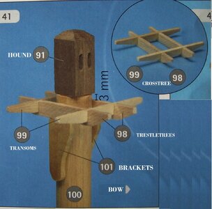
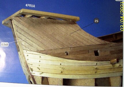
According to the instructions, the 10mm dowel from which the mast is to be made, must be tapered to 9mm at the top. Then the crosstree (made up of trestle-trees and cross-trees) and the cheeks are glued. But, apart from the non-ideal gluing of a flat surface (the cheeks) on a round one (the mast), it seems that the appearing of the cheeks is later. The Nao di Matarò has the cross that supports the top, but no cheeks: coffa nao matarò.jpg Giona.jpg Also in the Bronze relief "the sacrifice of Jonah". It is located in the Basilica of St. Anthony in Padua and dates back to 1514.
Moreover, as seen in a previous drawing, there are at least eight different solutions that exclude both cheeks and crosstrees; however, one of them involves four supports radiating from the shaft.
Other simplifications and approximations.
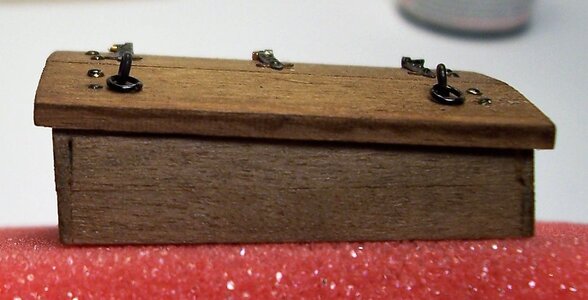
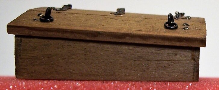
The crosstrees: the photos of the instructions and the drawing give two contrasting visions: in the first one it is almost flat (in the red ring), in the second one and in the drawing the trestle-trees are at a different level from the cross-trees. This affects the positioning of the blocks, the stay and the Jakob's ladder:
b.JPG a.JPG e.jpg

The placement of the blocks: from the drawing it seems that in the blocks (B) the rope does not run along the throat of the pulley, as if they were positioned upside down: c.JPG Also the halyard going through the mast hound seems to be inserted UNDER the pulley (and the same is seen for the rack on the deck and the halyard block).
The halyard: based on the drawing, it would not seem possible to raise the yardarm to the top, as the block is too close to the rack:

h.jpg

The jakob's ladder: 
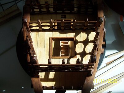
rope ladder to reach the top of the tree. It is not clear how it ends: it seems to be nailed to the base of the top (point F) in a way that seems to make entry impossible:g.jpg From documents of the time it can be seen that the rope ladder could continue to the upper edge of the top or it was possible to access from an opening at the base of the same.
The blocks: the blocks in the package do not seem to be suitable for the era of the Cocca; they should be good for ships of later centuries. Their dimensions are about 7.2 x 4.5 mm (I think they would be good for vessels in scale +/- 1:70 to 1:90, from the seventeenth century to the late nineteenth century):100_1100.JPG

The blocks of medieval ships in the illustrations of the time.
The model of the Nao of Matarò has blocks very different from those included in the package; they are visible in several images posted above. Contemporary (or slightly later) images also show blocks of very different shape (some seem to be painted dark/black at the ends, perhaps something protective against humidity, salinity):
100_0846.JPG100_0847.JPG100_0849.JPG100_0858.JPG (from V. Carpaccio's paintings).

Next time, we'll try to overcome these simplifications and improve the final result.

See you later!

Rodolfo
 

Attachments

  • masthead.jpg
    masthead.jpg
    265.9 KB · Views: 3
Welcome, friends!
as we have seen, medieval ships have blocks very different from those included in the package, perhaps painted dark/black at the ends.
A review of the main types of blocks used in the Middle Ages can be seen in the following image, which collects drawings from various sources:rassegna di bozzelli.png
Types of blocks in use in the Middle Ages and beyond. Images collected from : "Anatomy Of The Ship -The Ships of Christopher Columbus" by Xavier Pastor and from: "Sàrtie, Mediterranean Style" by Pino dall'Orco.

BLOCKS: there are manufacturers who have in their catalogs blocks of fine workmanship, but not always of the required size and sometimes not available, as small series production.
Perhaps the shortest way is to build them yourself: you slice a few wooden laths and rods of various sizes, file them to the desired size and assemble. The shape is then given to them with file and sandpaper work, also using templates:
k.jpgk2.jpgk3.jpgk4.jpgk5.jpgk6.jpg

The central round area that recalls the pulley pin is simulated by digging a surface hole and sanding after putting a trace of glue. The glued sawdust will vary just enough in tone to give the impression of the existence of the pulley pin.

For the Mediterranean Coca, the dimensions used range from 7 to 12 mm for the length, from 3 to 6 mm for the width, and from 2.5 to 3.2 for the thickness. Obviously, the double and triple blocks grow additively in thickness. Not being there absolutely certain documentations, everyone can enjoy certain freedom in the construction of these details essential for the good success of the model.

See you later,

Rodolfo
 
Back
Top