
Wait a sec! Amati makes triangular deadeyes?!Very nice work Kurt.I am impressed by the results of the block buster,the blocks look so much better for rounding off.I admire your patience reshaping all the deadeyes,I would have given in and ordered the triangular ones produced by Amati.
Looking at the Sovereign pictures,it reminds me why I subscribed but it is sad how different the model supplied was to the pictures shown.
Kind Regards
Nigel

You are using an out of date browser. It may not display this or other websites correctly.
You should upgrade or use an alternative browser.
You should upgrade or use an alternative browser.
La Couronne Corel/scratch 1:100 First build [COMPLETED BUILD]
- Thread starter DARIVS ARCHITECTVS
- Start date
- Watchers 52

Wait a sec! Amati makes triangular deadeyes?!
Yes Kurt,They did last time I browsed the catalogue
Kind Regards
Nigel
Thanks Nigel! You just saved me about 30 hours of work sanding and filing SOME of the round deadeyes into triangular shapes by ordering a pile of triangular deadeyes from Cornwall Boats Ltd in UK, for both La Couronne and HMS Sovereign of the Seas.Yes Kurt,They did last time I browsed the catalogue
Kind Regards
Nigel
Regarding the Sovereign, the pictures of the as-sold kit and the original model made by DeAgostioni make me want to cry. I have the DeAgostini kit, and will have to bash the hell out of it to bring it up to acceptable standards. I'm not looking forward to redesigning the entire shape of the stern.

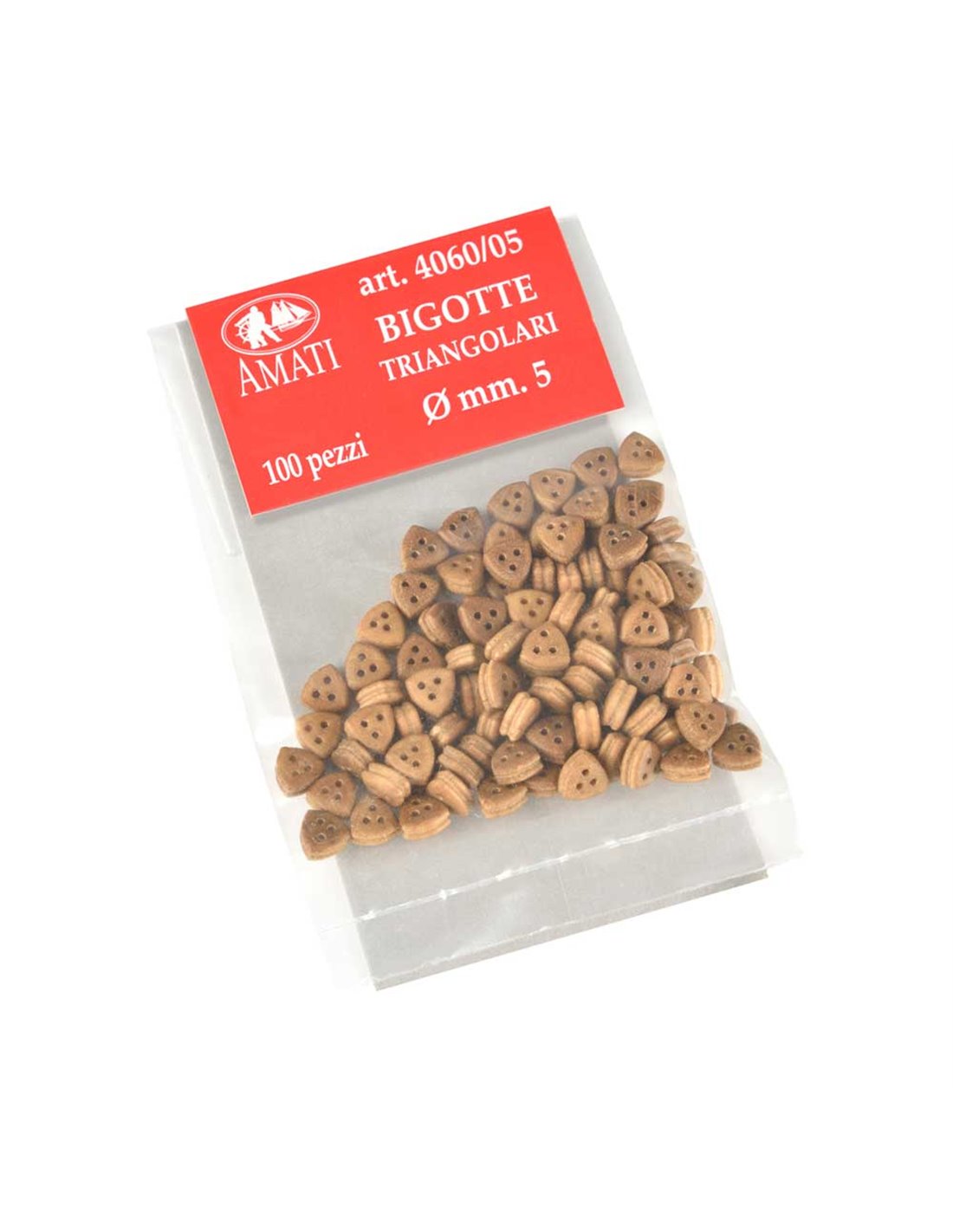
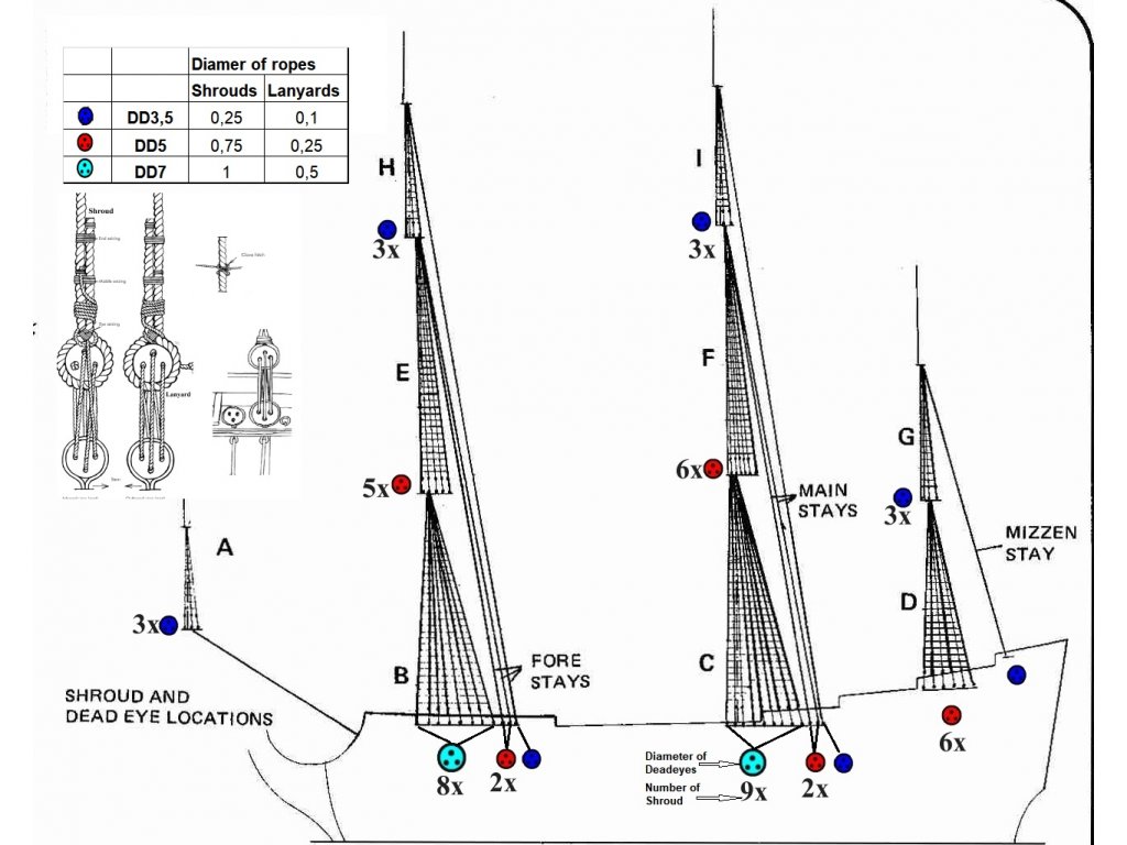
5mm and 7mm

 store.amatimodel.com
 store.amatimodel.com
Amati Model - Triangle deadeyes mm.7 - Fittings and accessories
Triangle deadeyes mm.7
store.amatimodel.com
Amati Model - Triangle deadeyes mm.5 - Fittings and accessories
Triangle deadeyes mm.5
store.amatimodel.com
Those are the ones. I bought a huge pile of them, since they will be needed on the next ship too. Too bad Amati doesn't make any 3mm triangular deadeyes.

Vincenzo Lusci's book Costruiamo insieme il modello de La Couronne, Vascello francese del 1636, states:
"Nella Couronne peraltro le bigotte dovrebbero essere triangoleggianti (bigotte a
cuore)."
"In Couronne, however, the blocks (deadeyes) should be triangular (heart shaped blocks?)."
This is not the first time I have seen references to early 17th century deadeyes being triangular as opposed to circular in shape. The deadeyes on the DeAgostini model of HMS Sovereign of the Seas are triangular. (the model which the kit is based on, not the ship created using the kit). Since La Couronne is an early early 17th century vessel, it made sense to make the deadeye shapes using this older shape than the round deadeyes provided in the kit. So, based on this information, I decided to reshape all the deadeyes in the kit to triangular. This will lend an older appearance to the vessel, setting it apart from later ships build in the 1650's. It also means I have to file each of the 180 deadeyes, since no one I know makes triangular commercially. Tonight I got through 74 of them. All 72 of the 7mm deadeyes, and two of the 3mm deadeyes (very tiny!) were reshaped. New chain plates were purchased from Model Expo to replace the kit ones. This is because the kit chain plates were made of wire and looked cheap, and the new ones needed to be a bit longer due to the changes made when I moved the channels down below the upper gun deck. They needed to be a few millimeters long in order to reach their attachment points on the wale located below the lower gun deck. The top portions of the new chain plates will be reshaped to the new triangular shape to accommodate the deadeyes.
View attachment 132589
View attachment 132590
View attachment 132591
Examples of triangular deadeyes on ORIGINAL DeAgostini HMS Sovereign of the Seas.
View attachment 132594
View attachment 132593
View attachment 132592
Kurt, are you sure about the triangle deadeyes for Sovereign of the Seas? I haven't seen this before anywhere. I am building SOS and do not want to bother about those triangles!
Janos
I guess also, that at this period, they used already the rounded deadeyes and not any more the triangular one - but in moment I have no chance to prove it with a publicationKurt, are you sure about the triangle deadeyes for Sovereign of the Seas? I haven't seen this before anywhere. I am building SOS and do not want to bother about those triangles!
Janos
see f.e. here, but this is for me no prove:
Soleil Royal - set of 218 pcs wooden Deadeyes - variant 2 of Standing rigging - HiSModel
Soleil Royal - set of 218 pcs wooden Deadeyes - variant 2 of Standing rigging. Standing rigging - Deadeyes - variant 2. According to the correct documents from that times, the rounded Deadeyes were used on the ships of the given period, and not triangular, as in the Heller kit. However, if you...
Standing rigging - Deadeyes - variant 2. According to the correct period documents, the rounded Deadeyes were used on the ships of the given period, and not triangular, as in the Heller kit
Those are the ones. I bought a huge pile of them, since they will be needed on the next ship too. Too bad Amati doesn't make any 3mm triangular deadeyes.
I guess that the necessary information is shown in the book from R C Anderson "The Rigging of Ships - In the Days of the Spritsail Topmast 1600-1720"Kurt, are you sure about the triangle deadeyes for Sovereign of the Seas? I haven't seen this before anywhere. I am building SOS and do not want to bother about those triangles!
Janos
I will try to take a look in the evening, when I am at home.....
Actually Uwek, I was using the DeAgostini original model as my source. Soleil Royal was made much later (1670), so it doesn't compare well to SotS. Build dates are for La Couronne 1635 (1636) and HMS Sovereign of the Seas 1637. There are no hard rules as to when and where triangular deadeyes went out of favor, and some ships retained early design features late into the 17th century. I chose to build La Couronne (and later SotS) with triangular deadeyes based on age of the ships, and borrow some of their assumptions a few other modellers made too. Even if SotS had triangular deadeyes in 1637, by the time it was rebuilt in the 1660's, those deadeyes could have easily been replaced. Ships get new masts every few decades, and small changes are rarely documented. Most of the details we choose to use in models this early are just guesses.I guess that the necessary information is shown in the book from R C Anderson "The Rigging of Ships - In the Days of the Spritsail Topmast 1600-1720"
I will try to take a look in the evening, when I am at home.....
Another issue is the use of belying pins on 1630's ships. It's highly debateable, and some ships may have used them long before they became popular. The DeAgostini model used belaying pins. If I choose to remove the pins, then I have to come up with a system of tying all the sheets and halyards to mast cleats, kevels, shrouds, and railings. At this point, I need to gather all the evidence about how to tie those lines on early ships as I can, and there's not much at all.
Last edited:
The foremast was glued in place in the forecastle. The mast alignment jig was used to make sure it was vertical. A 6" long liquid carpenter's level was used to make sure that the hull was perfectly level. A piece of a drill bit was used as a pin for the mast, but before the drill bit was broken to obtain the shank for the pin, the bit was inserted into the hole drilled into the bottom of the foremast. The angle of the drill bit in the mast was checked by turning the mast in my fingers with the tip of the bot on the table. Any misalignment was corrected and the bit was glued temporarily into the end of the mast. The mast itself was then used to drill the hole in the upper deck (which is below the forecastle deck) using the bit while ensuring the mast was vertical. Certainly there are easier ways to step the mast into place, but this was quick, and after applying PVA glue to the bottom of the mast, the pin ensured that the alignment of the mast was good. A final check was made with the alignment jig, and the lowest section of the foremast lined up perfectly with the string of the plumb bob.
Using thin pieces of shaved wood, chocks were added to the surface of the bowsprit behind the collars for the blocks installed earlier. This was a small detail, but every detail counts when the model is finished.
All the 7mm deadeyes were stained with Danish Oil (Walnut). A couple of the 7mm deadeyes and chain plates were made as a start to preparing the chainwales for rigging of the shrouds. The new chain plate sets from Model Expo were used instead of the simplified ones supplied by Corel in the kit. The brass wire surrounding the deadeye was round, and this portion of the wire was straightened, then reshaped into the triangle to hold the 7mm triangular deadeye reshaped earlier. The lower chain plate double eyed link and the copper flat plate were assembled onto the upper chain which holds the deadeye. Before the wood deadeye was inserted and the wire closed around it, the chain plate assembly was blackened with brass blackening solution. At the bottom of the deadeye, the ends of the wire are butted, but but soldered. I know it's a better practice to solder the connection, but the break in the wire is too close to the wood in this design, and soldering would char the wood, and leave a silver shiny spot that requires painting later. The wire appears to be stiff enough to take the stress of the shroud tension without bending the deadeye loop open. The open wire joint will be hidden fairly well between the deadeye and the chainwale, and any gap can be filled with a touch of glue and paint.
Amati chainplate assemblies will be used instead of the Corel ones. Some of the chainplate assemblies were made and the foremast chainwales were marked using a temporary false shroud line. Notches were cut in the chainwales with a Dremel tool and cutting wheel, then filed to final depth and shape to accept the chainplates on both sides of the hull for the foremast. The chainplate assembles were blackened in a glass bowl, then small needle nose pliers are used to bend the chainplate parts to place the deadeye in the correct angle at the top, and form to fit the wale on the hull at the bottom. The ship hull was tipped in its side to allow me to work easier. Two back pins were used to nail the bottom of the chain plate to the wale and hull. The upper pin was installed first, being held with pliers in my left had while a tack hammer was used to tap the pin into the hull with my right hand. The final taps were made with the jaws of the pliers touch the pin head to set the pin all the way in. Since all this fitting and working rubbed some of the blackening off the chainplates, they were painted black with a small brush once they were installed. More chainplate assemblies need to be prepared and installed next, after which a strip of walnut will be used to cover the the outboard edge of the chainwales.


Chainplates and chainwale trim are completed on the starboard side for the foremast.

Port side chainplates are complete for the foremast shrouds. Note that the dog bone piece of each chainplate has to be resized so that the anchoring part at the bottom rests on the wale. Small round jawed need nose pliers are used to reform some of the dog bones to make them shorter as necessary. The loose chainplates that appear out of aligniment at this point will pull taut once the shrouds are installed. That way each chainplate will be aligned perfectly with the axis of each shroud respectively. It was tricky relocating the chainplates and chainwales such that nothing will interfere with the line of sight of any of the guns. However, relocating the chainwales is a more accurate feature for many ships of the early 1600's. Mantua's La Couronne is built this way, but Corel's is not. I prefer the Corel stern design over Mantua's because the height is more realistic and not derived from an artist's woodcut or painting, which often tends to romanticize the sheer curvature and stern gallery height to an impractical extreme.

In preparation for installing the main mast shrouds, the main mast was pinned and glued into place. The plumb bob jig was used to make sure it is lined up with the foremast, vertical but with about 3-4 degrees rear rake angle. More nailheads were painted onto the tops, topmast cheeks and topgallant cheeks. After the glue for the mast started to get firm, the mast cover was let slip down the mast and glued to the deck. The mast cover is what covers the mast wedges that anchor into position in the upper deck.

Main mast top

Main topmast top

Main topmast cheeks

Mizzenmast top

Mizzen topmast cheeks

Foremast top

Fore topmast top and cheeks

Main mast wedge cover at the base of the base of the mast on upper deck

Main mast top
Main topmast top
Main topmast cheeks
Mizzenmast top
Mizzen topmast cheeks
Foremast top
Fore topmast top and cheeks
Main mast wedge cover at the base of the base of the mast on upper deck
The chainplates for the main mast on the starboard side were assembled and installed today. I can't complete the ones on the port side until some parts come in from Modeler's Expo. First, the locations of the shroud lines need to be determined. They need to be placed such that they don't block any of the cannons. A line tied to the mast top is used to mark the line locations on the edge of the chainwale. The line is laid over each mark on the chainwale to locate and mark where the chainplates will attach to the hull. It's important that the chainplates run parallel to the shrouds when the hull is viewed straight from the side.
The process of nailing the chainplates to the hull is simple, even though the parts are small. Each individual chainplate assembly is adjust to the correct length for each place on the hull by shortening the dogbone link to the required size, siuch that the upper nail position is on the wale on the hull. The upper nail is held with a small needle nose pliers, the nail inserted into the hole in the backing link of the chainplate, and hammered into the wale with a tack hammer. The nail head was set using the end of a needle file tang using the tack hammer. The angle of the chainplate is checked to see if it is parallel to the shroud line, then the second (bottom) nail is hammered and set into place. When all the chainplates have been nailed in place, a 2m x 2mm strip of walnut wood is glued to the outboard edge of the chainwale. CA glue was applied near the edges and at one spot in the center of the chainwale, and PVA glue is applied along the remaining areas of the edge. When the wood is pressed into place, the CA glue binds immediately and holds the piece in place while the PVA glue dries. It's faster that holding the piece in place for 20 minutes waiting for it to hold. A small detail brush is used to paint the chainplates black to cover brass that was exposed by handling and shaping the chainplate parts.
The mizzen mast was glued into position on the ship. A nail with the head cut off was glued into a hole in the base of the mast. The mast was test fit, lined up, then the mast head was tapped with a track hammer, such that the nail in the mast bottom pierced the deck below. The mast was then pull back out, glue applied, and glued into place. The coat was the slid down and glued to the bridge deck.
A correction was made. I installed 9 chainplates on each side for the foremast, when there should be 8. So, I removed the rearmost ones and patched the holes in the chainwales. Oops....
CORRECTION AGAIN 4/2/20: I put the chainplates back a bit later, so there are 9 on each side. The backstays will not have their tackles on the channels, but attached to the hull on the wale above the channels.

CORRECTION AGAIN 4/2/20: I put the chainplates back a bit later, so there are 9 on each side. The backstays will not have their tackles on the channels, but attached to the hull on the wale above the channels.
Last edited:

Hi Darivs,
I have build La Couronne too but the Mantua version, a bit different from yours but it's a beautiful ship. I had so much fun and you are doing a great job as first model, I like that blu and the leds inside the ship makes it even nicer. Well made precise and clean congratulations! I will follow you to seethe progresses
I have build La Couronne too but the Mantua version, a bit different from yours but it's a beautiful ship. I had so much fun and you are doing a great job as first model, I like that blu and the leds inside the ship makes it even nicer. Well made precise and clean congratulations!
I will follow you to seethe progressesVery good good looking progressHere's a cost update. The attached spreadsheet shows all model related expenses, including tools, research books, custom parts, and materials. The total cost so far is $2595.31 US.

Sometimes it is better not to remember and collect all the bills we are making ....... especially tools and power tools are for every and should be depreciated over a minimum 100 models, or better 1.000 models => with this trick the costs are much much lower
Installation of many blocks in preparation for rigging was done in various parts of the ship. Blocks which are part of the tackles which haul the main course yards in a downward direction were attached to the deck on front of each mast. Correction 4/22/20: Corel shows a lines leading from the main course yardarms to a tackle attached to the deck in from of each mast. These made no send to me, because there is no reason why you need a tack to haul a yard DOWN. So, these three blocks lashed to the deck will be used for the toprope tackles, which are used to haul the topmast aloft in a telescope-like motion when setting the topmasts in place in the shipyard. Later on in the build, these blocks were replaced with double blocks.
For all blocks, the eyelets were attached to the stropping of each block. The ends of the stropping line for each block was held to the block by using black thread to seize the ends, one end of which passed through the eyelet first. The seizing was secured with CA glue. The shanks of the eyelets were then glued into holes the deck. Blocks and eyelets which secure the port and starboard hoist tackles when they are stored were installed in the waist of the upper deck. Cleats were attached to the forecastle deck directly behind the catheads. These will be used to secure the line which the cathead uses to hoist the anchors, port and starboard.
Since I plan of storing two anchors on each side of the ship on the forward channels, two timberheads were added aft of the forecastle. for tying off the lines for the tackles used to maneuver the anchors into the rear positions. This arrangement will be more evident later when the anchors are installed. Eyelets with blocks having hooks attached were installed on the forward channels for anchor handling tackles for the anchors. stored in the forward positions.
The fiddle blocks for the tackles of the fore topmast backstay and the two main topmast forestays on each side were prepared. The bitter ends of the stropping line were glued together with a small amount of CA glue. Then an elongated hole was drilled onto the top of the block. The ends of the stropping line are inserted and glued into this hole, such that the stropping line forms a loose loop above the block. The loop is then inverted, being folded over the block and the line is glued to the sides of the block. The excess loop, now at the bottom of the block, will be used to form and eye. Each lower fiddle block had an eye formed in the stropping line, formed with a seize at the bottom of the block. To this eye, a wire hook is attached, using needle nosed pliers to close the loop at the top of the hook. The hooks were made from blackened wire using a round nosed pliers and regular flat jawed needle nosed pliers. The upper fiddle blocks for the backstay tackles will be rigged later when the backstays are installed.
Last edited: