• LUCZORAMA SHIPWRECK SCAVENGER HUNT GIVEAWAY. 4 Weeks of Fun • 1 Legendary Prize ((OcCre’s Fram Ship)) • Global Crew Welcome!
    **VIEW THREAD HERE**

Panart Royal Caroline

Joined
Aug 26, 2020
Messages
450
Points
278

Location
UK Dorset
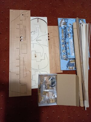
The box.
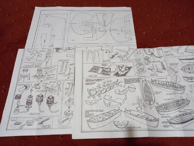
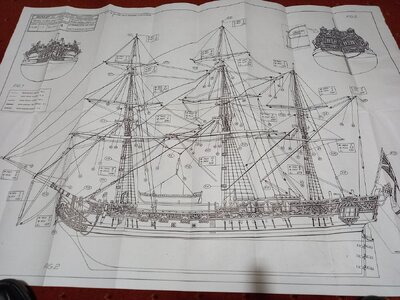
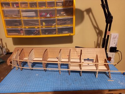
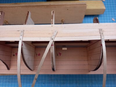
Standard ingredients: laser cut plywood sheets, planks, dowels, strips, rigging thread, plans and lots of shiny fittings. For reasons unknown the bulkheads are distributed over two plywood sheets of different colour and slightly differing thicknesses. The plans have a hand drawn appearance and are a bit approximate.. I took a lot of bulkhead measurements off a sheet purportedly representing the plywood sheets 1:1 only to find later that the actual bulkheads were different so I had to do it again. The keel and bulkheads fitted together very well. Some sample photos appended
First stage planking.
I hope at the second stage to bring all planks to the stem with a reasonable width (no points) rather than have the lower level planks curling up to meet the upper levels at an angle part way along the hull. This will involve tapering and, probably, a few drop planks.
By way of a rehearsal I chose to adopt the same approach to the first stage planking although a less formal approach would normally be used.
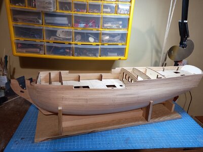
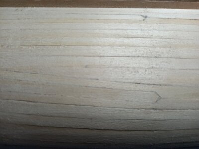
I was almost successful in this but was slightly derailed by the instructions. A line is specified on the plans for a starting plank. I followed this but the plank needed a bit of sideways force to comply. Instructions indicate five more planks below the starter with no tapering. The perimeter of the first few bulkheads is, as usuual, a lot less than that of the midship bulkheads. This instruction would plank over a lot of the precious space on the forward bulkheads so I tapered them a bit. I should have tapered them more and possibly included a drop plank. So I did end up with a few lower planks curling up to meet hight planks at an angle. A useful lesson to be applied at the second stage. I included a few formally shaped drop planks at the first stage as an exercise rather than the normal practice of leaving lune shaped gaps to be filled with pointy ended inserts. After dilligent application of my new scrapers I have ended up with a reasonably satisfactory result. There are a few small gaps and a bit of a mess low down at the stern deadwood but nothing that cannot be bridged with the second stage planking.
I used bow blocks shaped to continue the line of the first stage planking ready to receive the second stage
There is a small hole in the port bilge! I forgot to leave access to a screw that was holding the inverted assembly to a temporary support.
During the planking I pinned the planks to the bulkhead through 4mm wide strips of thin plywood. This made it easy to extract the pins without having to dig them out of the plank surface.
Box1.jpg plans1.jpg plans2.jpg
Frames.jpg first plank1.jpg
firstplank2.jpg drop planks.jpg
nailing.jpg
 
I like this ship model kit very much - I have also one unstarted in the shelf ...... maybe once .....
Have fun with this lovely model
 
Lining off the hull
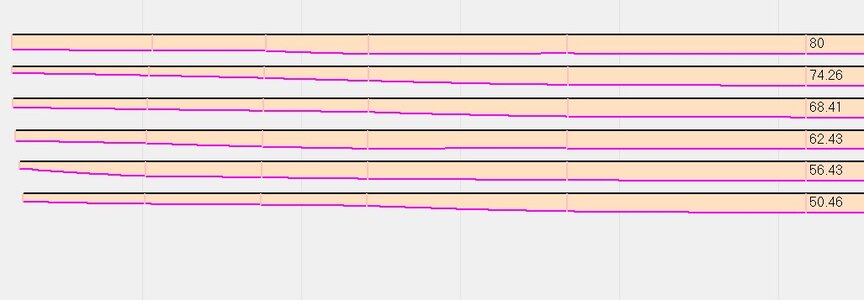
Rather than faff about with bits of string and tape I have written a piece of software to plan the second stage planking. Given a starting height on the widest bulkhead it calculates the natural line taken by a plank as it bends around the bulkheads towards the stem and stern. It also calculates the distance, measured from the keel, round the edge of the bulkhead to the line of the plank. Given two starting lines it evaluates the number of planks of nominal width that will fit between them on the widest bulkhead and the reduced widths on each bulkhead towards the stern and stem. It therefore gives the average tapering for a band of planks.
data for belt between 80 and 44 = 6 whole planks
bulkhead 1.0 2.0 3.0 4.0 5.0 6.0 7.0 8.0 9.0 10.0 11.0
band top 80.5 76.5 76.2 77.7 79.2 80.0 79.8 79.5 79.2 78.5 78.6
band bottom 62.4 54.3 50.8 48.1 44.9 44.0 44.7 45.4 46.5 52.9 59.6
keel to top 73.5 76.9 90.7 105.3 119.9 125.9 121.3 115.7 109.9 104.3 123.5
keel to bottom 55.4 53.0 63.8 74.6 84.7 89.2 85.4 80.7 75.6 70.5 86.3
band width 18.1 23.8 26.8 30.7 35.2 36.7 35.8 34.9 34.3 33.8 37.2
plank width 3.0 3.9 4.4 5.0 5.8 6.0 5.9 5.7 5.6 5.5 6.1
There are various options for displaying the planks.
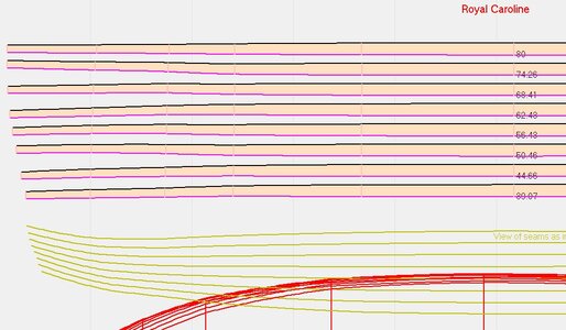
The first screenshot below shows the profile of planks as they would lie on the hull if they are all given the same taper identified above and allowed to follow their natural curve. The top of each plank is defined by the bottom edge of the one above. Ideally they would all be straight but use of a common taper means there is a bit of lateral bending to make them fit. It is probably small enough to be accommodated.
The green lines are a view of the seams as they would appear on the hull. The red lines are the edges of "decks" at each plank top.
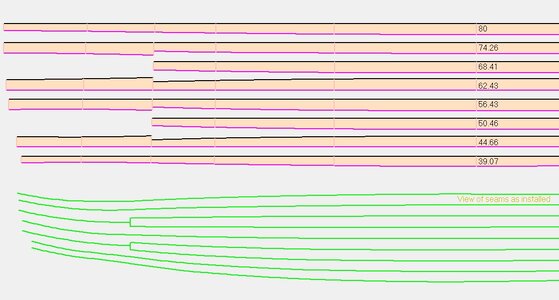
Alternatively, the second screen shot displays the profile if each plank follows its natural curve and its width is defined by its neighbours. . (Development is needed to correct the junction between first and second planks.) The planks would need not lateral flexing but their widths vary from plank to plank. This gives some indication of how narrow some might become at the stem. This is more of academic interest than a practical option.
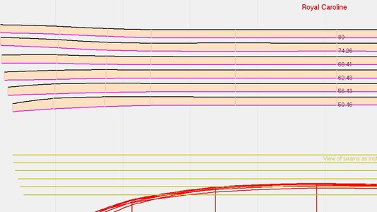
The third screen shot is a variation of the sfirst showing the effect of inserting drop planks. This option could be used to investigate where the drop planks are best inserted an how often
Finally, the fourth shot shows the (approximate) shape that the planks would have to be cut to maintain level seams along the lenth of the hull.
The upper planks would need to curve upwards towards the bow to counter the effect of the tumble home. The lower planks would need to be cut with a downward curve to counter the usual upturn around the fwd bulkheads.
The actual screen displays from which these clips are taken extend to the stern. There are some peculiar shapes under the counter!
The software gets a bit wobbly very low down on the bilge. A different algorithm is need to calculate the lie of the near-horizontal planks.
planks80.jpg individual.jpg
dropplanks.jpg
spiled.jpg
 
Second stage planking.
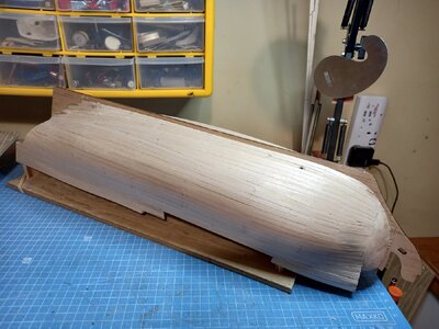
This has been completed. The surface is not a even as I would wish; the first stage was better. With the insertion of a few drop planks I managed to get all the planks running from stem to stern without any discontinuites in the flow and with reasonable widths arriving at the bow. Perhaps with a bit more scraping and sanding, a bit of filling and thick coats of white paint below the waterline it might be passable. The planking would have been a bit easier if the model had a few more bulkheads: some of the spacings were too great to provide firm support fot the plsnks. The planking above the water line is fairly presentable for varnishing.
I have constructed a rough box with the top surface at the waterline and a ship-shaped cut out. I'm not sure what purpose this serves but it was an excuse to play with my new toy - a Proxxon scroll saw. The box may provide a useful way of supporting some of the items on the upper hull. For example, the final picture below illustrates the potential for restraining the wales while the glue sets without having to insert pins. It may help in marking/taping the waterlinr for painting since trying to mark with the aid of a planking strip would create a curve,
2nd_planking1[1].jpg 2nd_planking2[1].jpg
2nd_planking3[1].jpg Waterline1[1].jpg
Waterline3[1].jpg Waterline2[1].jpg
 
Gun tackles.
The smallest blocks supplied with the kit seem rather large to be used as part of the gun tackles so I have chosen to make some smaller ones.
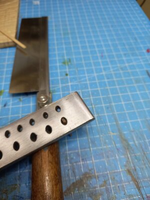
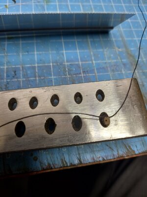
I tapped (does this count as literally kit bashing?) a length of 3x2 mm walnut strip through an oval hole in a draw plate until it protruded by about 1mm.
This nicely rounded off the corners.
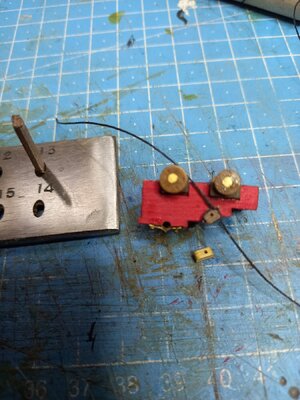
I then sawed a shallow groove round the end and drilled a hole. After tying a strop I bashed the srip a bit futher and sawed off the end.
The third picture below shows the result temporarily liad on a gun carriage and a kit-supplied block for comparison.
Ideally the strop should be wrapped around the flat ends of the segment and the hole drilled through the side but this would make production more difficult for minimal improvement in authenticity. I wimped out of making double blucks; Jolly Jack will just have to pull harder.
gun tackle1.jpg Gun tackle2.jpg Gun tackle3.jpg
 
Dead eyes
Every time I get to the stage of fitting the upper rows of deadeyes I seem to try a different method. Some more successful than others but it provides a bit of variety and opportunities to experiment. I have tried various devices with bits of wire, tried building shrouds on a bench top jig or simply tying the second end of each shroud pair on the hoof in an adjustable loop.
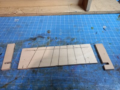
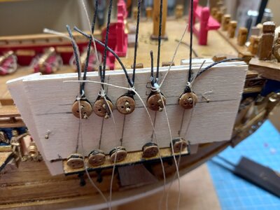
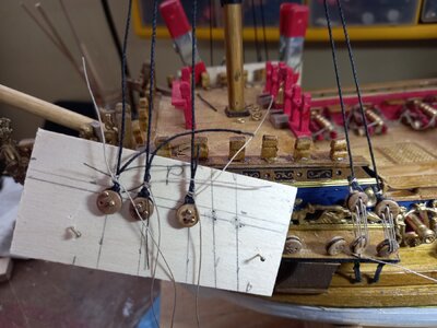
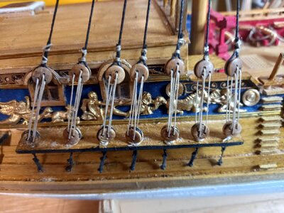
The latest approach is to pin the upper layer deadeyes to a board then secure it temporarily on the chain plate. Photo 1 below shows the basic "kit". The line of each shroud is marked on a plywood board using a test cord tied to the masthead. The notched strips hook around the end of the chain plates and keep the prepared board in place. The second photo shows the board in place with the upper row of deadeyes pinned to it. This was done on the bench using the markings on the board. The pins are pushed into pilot holes for ease of removal later. Two pins maintain both height and orientation. The shrouds have been tied round the upper deadeyes. In the third picture the board is removed and the deadeyes unpinned one-by-one and laced to the lower deadeyes. The final picture shows the end result: the deadeyes are reasonably aligned and the shrouds have a uniform tension.
The process requires a bit of preparation time but not a lot. It is probably recovered in the step of tying the shrouds around well fixed deadeyes. A few refinements in the details and the sequence of tying on the lanyards were made as I worked on successive masts/sides.
deadeye board1.jpg deadeye board2.jpg deadeye board3.jpg deadeye board4.jpg
 
Ratlines
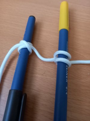
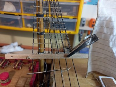
This is the first model I have built on which the ratlines and shrouds have different coloured threads. Formerly the clove hitches were just amorphous blobs at their intersections but now the contrasting colours highlight the detailed structure. This is exaggerated in the first photo below. On one side the two half hitches form a cross. On the other side the two half hitches appear as separated loops. While I concede that this colour difference is probably correct (tarred and untarred) I am not sure that I like the appearance and the tying requires an extra level of care. The knots need to be pulled tight to minimise the separation of the component loops while at the same time keeping the ratlines straight (any slack always seems to hang upwards or outwards - never down!) but not distorting the shrouds. Otherwise the shrouds end up like a failed astigmatism test. For the lower mast ratlines I used the thinnest thread in the kit (0.5mm I think) but something thinner might have been better. For the topmasts I may raid SHMBO's sewing box for some suitably coloured thread and hope that she doesn't shed a button from a brown blouse before I put it back.
By the way: I usually tie my clove hitches with the 'crosses' outboard and the twin loops inboard. Is this correct?
Clove hitch.jpg RatlineX.jpg
 
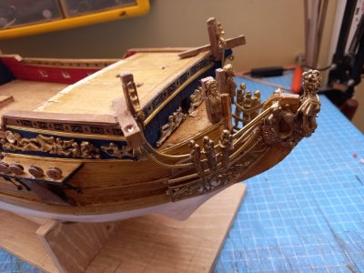
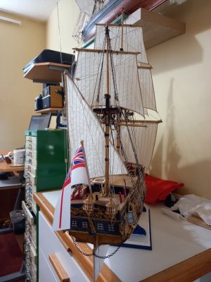
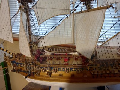
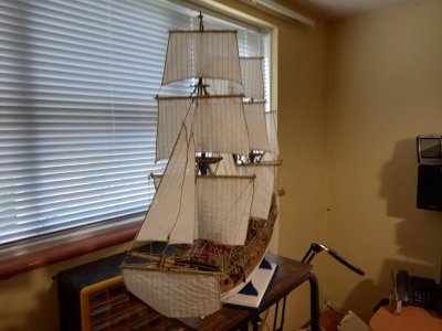
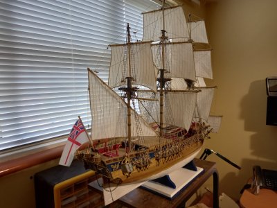
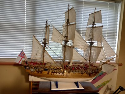
Royal Caroline Completed.
This was quite a good quality kit with generous supplies of good quality materials. Apart from the fine thread used for the ratlines and running rigging;. I ran out of this and had to dig into my stock of left-over OcCre threads. When will manufactures realise that use of the ratline thread incurs a lot of waste? Each end of every ratline has a bit that has to be trimmed off after the knots have been secured. (This same shortfall also happened on the Panart Cutty Sark kit.)
The instruction sheets were a bit primitive and appeared to be hand drawn. The important, full-size side view was inaccurate and misleading. I took measurements from it to position the wales and scupper holes but ended up with these at the wrong heights. The scuppers did not align with the decks and the supplied dead-eye hounds would not reach the wale as they should.
A set of castings for side decorations were well formed and bright. other castings for individual figures and figurehead were a bit dull and did not buff up very well.
The sail kit (extra) was quite good with a very narrow and tight hem around each sail that passes as a bolt rope.
Generally, the build was fairly straightforward.
dull castings.jpg RC_done6.jpg
RC_done1.jpg RC_done2.jpg RC_done3.jpg RC_done4.jpg
 
Back
Top