Princess Charlotte 1814

Dave Stevens (Lumberyard)

Sponsor: dlumberyard
Staff member
Sponsor
Joined
Dec 1, 2016
Messages
5,128
Points
728

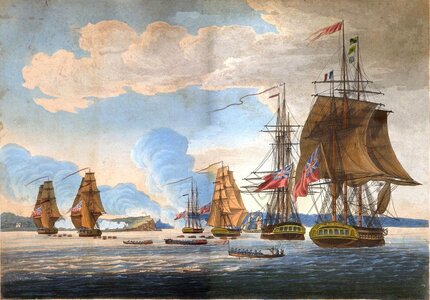
1814 attack on fort ontario.jpg

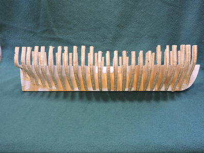
The Princess Charlotte has been in my archives for years, i started out thinking to build a plank on frame model but because the framing is almost a solid wall of timbering a plank on frame would look like a solid hull, so what's the point in framing the hull. The framing was massive 12 x 16 inch timbers with only 1 to 1 1/2 inch between frames as timbers fell apart and shifted some measurenents were recorded as 2 to 4 inch space. At 1:48 scale that would be about a fat 1/64th between frames, .020 thousanths. So the project went back on the shelf.
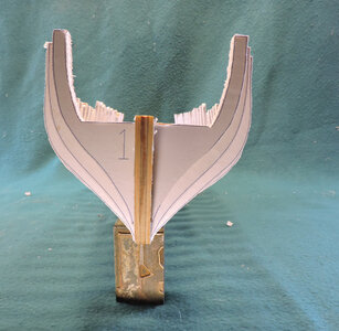
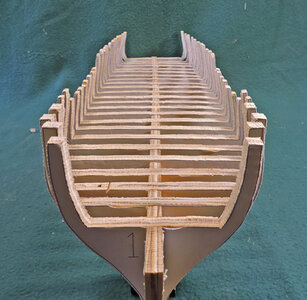
Going back i thought hum maybe a plank on bulkhead model, which i started and later abandoned.


In the back of my head and back off the shelf here it is again. This is a super frigate built on Lake Ontario during the war of 1812. she is one of a kind and played a historical part in the war on the lakes. It was built for the lakes and built for speed and fire power.


So why bring it up again?

The Princess Charlotte has a historical story to tell and the unique construction of the ship itself. Way back when i started model ship building sometime in the 1960s there wasn't anything like Google search if you needed information you sat down and wrote a letter to a museum then waited and waited. Any follow up questions took weeks on end to get an answer. If you wanted to build a ship model with actual frames, well that information was extremely difficult to find back then. Once wooden ship construction began to come available the term "room and space" became part of the general knowledge of the ship modeling community and applied to everything, because back then very few builders had access to infornation. The term room and space was defines as the space between frames were equal to the sided dimension of the frames. So a 12 inch frame had a 12 inch space. As i began to search through old ship drawings i came to a realization that was not always true, there were hull built with triple frames, frames spaced closer together and even in some cases no space between frames. Frame floors in some cases were one timber that sat on the keel then there was the long arm short arm floors. As information became more available to ship modelers the subject of framing got more and more complex.
Different countries had different methods of framing a hull, Framing evolved over the years, framing was different depending on what the ship was used for.
At some point around the late 1970s maybe 1980s it was all the rage in ship modeling for historical accuracy and the catch phrase "ADVANCING SHIP MODELING THROUGH RESEARCH" became the battle cry, That is well and good if you can afford the research, hire a researcher or make a trip to do the research. A grand idea just not very practical for your average hobby builder. Years ago someone found a framing plan in the Admiralty collection showing double frames and filler timber between the frames. Through the ship modeling community you heard "so that is how war ships are framed" true statement if you were a shipwright working in a royal shipyard in England in the 1700s or so but not anywhere else on the planet.


in closing just because you have a ship drawing and using general practices does not make it a historical correct model, unless you are working from a ship wreck with all the archaeological field work and data.

The Princess Charlotte was a British warship built in a British Royal shipyard by French ship carpenters in North America, you can bet this is
not your standard British built ship, so toss out all your ideas on British ship building. This hull has 4 different types of frame
construction in one hull.
charlotte 3 24.JPG

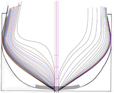
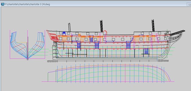
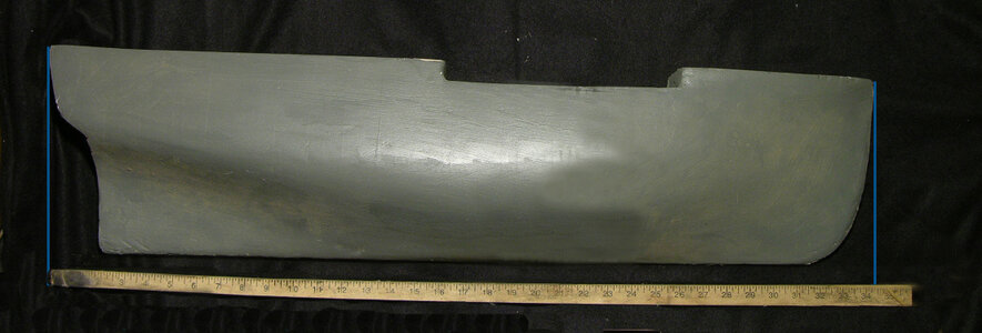
the hull had very little space below deck, the hull was very sharp at the bow and stern.
5967.jpg

012.jpg024.jpgbow view.jpg


https://www.youtube.com/watch?v=yhGrPq47TYU

https://www.youtube.com/watch?v=FPpYTZB-neo

https://www.youtube.com/watch?v=o5rsikoA3rg&t=49s

https://www.youtube.com/watch?v=Fxtg7O6HfPU&t=59s


an artical in the MSB Journal on framing


the unique design of the Princess Charlotte

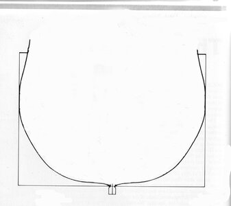
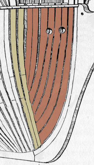
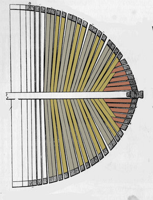
This is the mid section of a typical British 5th rate frigate

5th rate.jpg

the frames start with a floor timber that crosses the keel.

5th rate floor.jpg

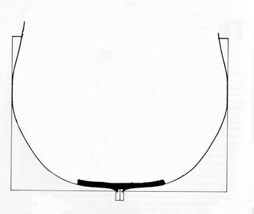
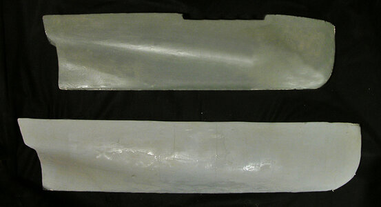
this is the Princess Charlotte over laid on the 5th rate. The ocean going ships were out for months on end so they need cargo space
food, water, and stuff. On Lake Ontario the Princess C was only out for a day cruise maybe a week or two. So what the designers did was trim
down the hull so it was fast and handled well and carried heavy metal. Interesting though, these two super frigates had a smaller schooners with them
Maybe they ran supplies to the Prince Regent and the Princess Charlotte.

5th rate pc body.jpg

the typical frame construction of a 5th rate is jusy not going to work for the Princess, not even close
 
Last edited:
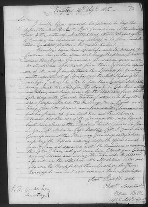
the man incharge of the building the Princess Charlotte was George Record who was appointed Master Builder at the Kingston yard after Daniel Allen was removed from that position due to the workers refusing to work because provisions that were promised to them where not delievred. Considering the fact the two frigates were being built during the winter in Canada in 1814 on the northern shores of Lake Ontario i guess the conditions were quite brutal. maybe they wanted better food, gloves and winter coats, snow shovels, boots, better living quarters besides tents, whatever.
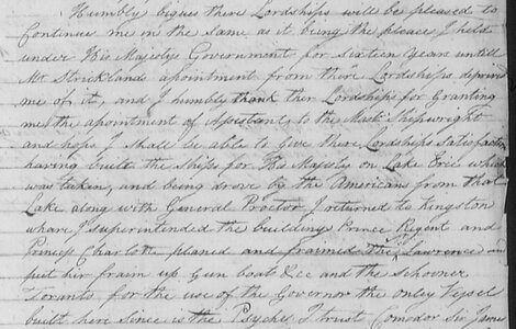
Two ships were under construction in the yard the Prince Regent under the supervision of John Goudie and the Princess Charlotte under supervision of George Record. Both ships were being built under contract. whether or not the grievances over provisions were settled the builders seems to be a picky lot because building on the frigates were at a stand still. This time the problem was the builders under Goudie were being paid more than the builders working under Record. Entering the yard was William Bell who was appointed assistant to the master shipwright at Kingston. William was the master shipwright at the British yard at Amhersburg and built the fleet on Lake Erie. After the Americans took control of Amhersburg William Bell was sent to Kingston. I might guess a delighted George Record had someone to pass the buck to, "William my man, glad to see you, we have two super frigates sitting on the stocks getting buried in snow and ice and no work is getting done, i need you to go out in the yard, take charge and get it done!" i do not know what William did but he somehow brokered a deal and both ships were launched on time. William took credit for doing that.

appointed to kingston1.jpg

looking closer William took credit for superintending the building of the frigates.

appointed to kingston2.jpg
 
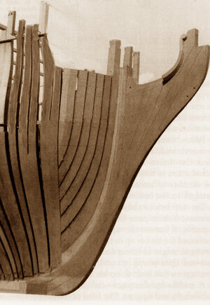
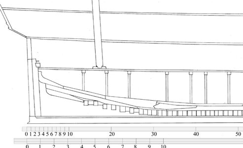
These are the scattered bones of the Princess Charlotte but still enough for a historical reconstruction

bow0.jpg
Starting at the bow which is the first of four different frame construction. Lets first take a look at how the British framed in their bows. Starting with cant frames and adding the bow timbers. a typical drawing showing cant frames and bow timbering
bow1.jpgbow2.jpg

A model would look like this

bow3.jpg

You can see this style of framing a bow in many contemporary models.
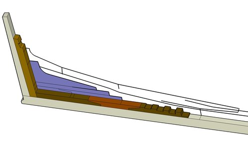
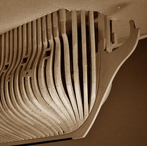
But that does not seems to be how the Princess Charlotte bow was built. One interesting method is the use of what looks like wedge shaped frames and there are no bow timbers drawn parallel to the keel. After the bow frames there are 47 green frames and that is the second way frames were built, which we will get into later.

bow4.jpg

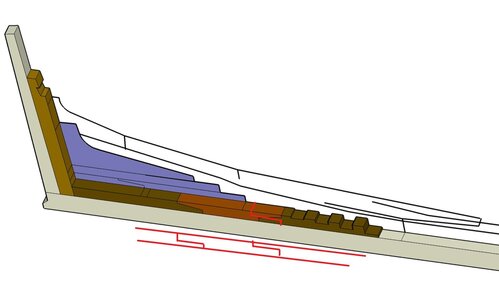
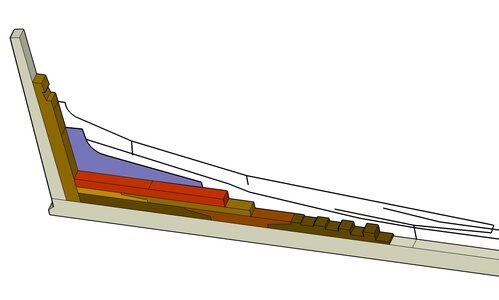
the framing of the Princess Charlotte bow looks more like this model which was built by Harold Hahn. By the way he took a lot of trash talk that his models were framed wrong. Actually as more data became available over the years and if Harold were alive today he would say to those elitist who thought they knew everything "i told you so"
bow5.jpg

this topic is not about building a model it is about hey look at this unique British warship and how it was built. So we are going to just fly right by the bow and move on to the keel and see what is going on there.
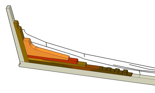
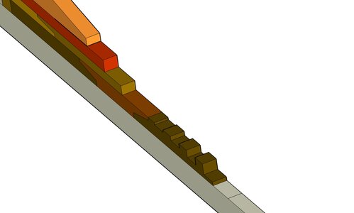
 
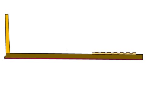
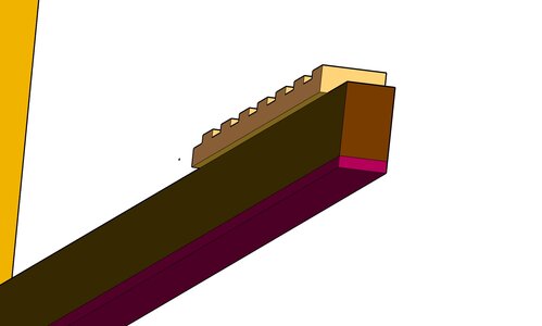
the keel is made up of 3 pieces a false keel at the bottom then the keel which is 12 x 16 inches and on top of the keel is a rising wood notched for 1/2 of the double frames. The rising wood runs from the deadwood at the bow and all the way to the rising wood at the stern, which is not shown yet.

so we all know where we are, we are at the stern now. The rising wood is only a small section it would run the length of the keel.

keel1.jpg
keel2.jpgkeel3.jpg

the rising wood is wider than the width of the keel which gives the gardboard a solid backing


keel4.jpgkeel5.jpgkeel6.jpg
 
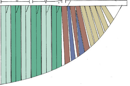
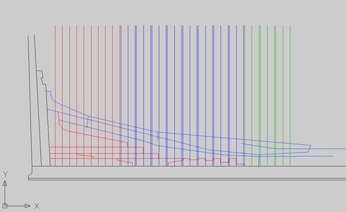
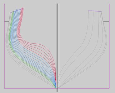
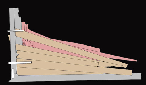
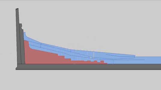
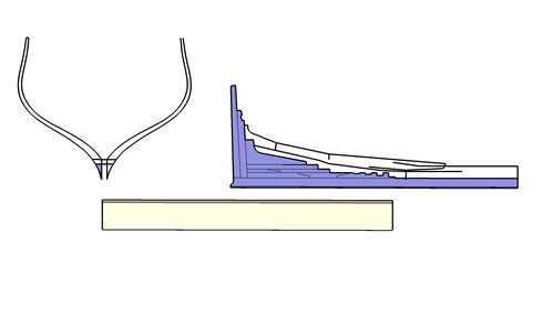
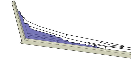
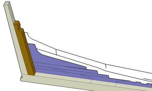
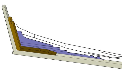
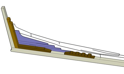
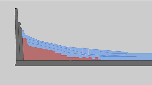
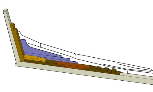
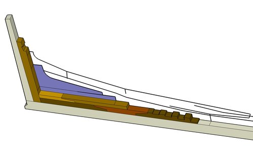
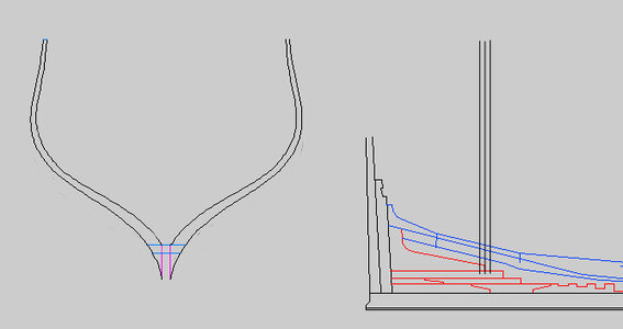
what i am going to do is a reconstruction of the stern section. Here we have 3 different systems for building frames. to the right are the green frames and they are the same all the way to the deadwood at the bow, next are the blue frames which sit on the rising wood these are 1/2 frames with a cross chock that sits on the rising wood and finally nine 1/2 frames that butt against the deadwood.

progress4.JPG

the frames involved are the colored ones.

progress3.JPG

the reconstruction is based on drawings done of the wreck.


stern frames.jpg


one small problem is the "fill in the blanks with your best guess". On the wreck planking covered the rising wood so there is no way to know how it was assembled.

stern drawing.jpg

One idea if you were to built a stern section is to make the rising wood one single big piece the red area, above it the blue area is deadwood and the end of the keelson. or take a guess.
I am going to take a guess of how to assemble the rising wood.


simple stern.jpg
 
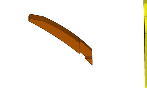
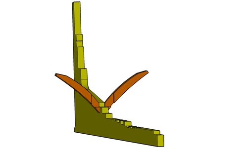
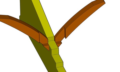
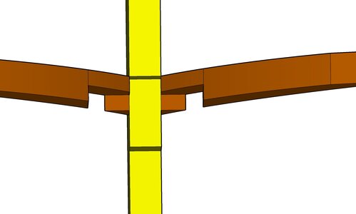
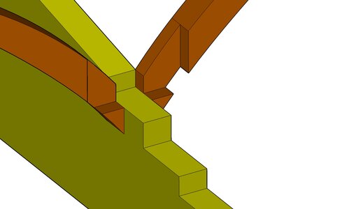
Taking into account the following data first the stern frames butt against the rising wood and have a cross chock that sits on top of the rising wood that joins the two floor timbers, so the rising wood has steps that the frames will sit on. Secondly that is a lot of rising wood and taking into account timber sizes the rising wood needs to be built up of several timbers.

What you are looking at is the keel, stern post, inner post and the timbers that will make up the rising wood. This is just my suggestion as there are so many different ways the rising wood could have beenn built.


deadwood 3d 1.jpg
 
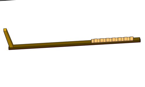
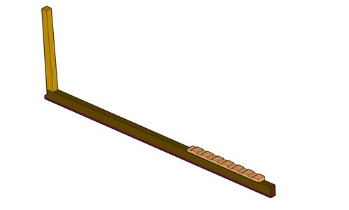
so timber by timber lets build ourselves some rising wood. first 3d model the keel and stern post which is 12 inches sided

deadwood 3d 2.jpg

then add the inner stern post, we know there was one because you can see it poking above the hull planking, it has a notch in it for a transom piece which happens to be laying on the lake bottom.

deadwood 3d 3.jpg
 
Hallo Dave,
a short question:
would the joints not going into the same direction?


yes your right a scarf would normally be the way you drew it. Because we do not know exactly how the rising wood was built it is up to your imagination.
The scarfing you see in the 3D model is called a butterfly and i have seen it on shipwrecks around the great lakes. I just thought it was something different so i used it here.
 
to continue with the rising wood

a model builder can skip all the pieces that would make up the rising wood and cut it from one piece

simple stern.jpg

but i will continue with the built up version. The next layer is 2 pieces scarfed together creating the next step up.

deadwood 3d 7.jpgdeadwood 3d 8.jpg

the timbers are getting shorter so there is no need to scarf timbers together

deadwood 3d 9.jpg

and finally the knee

deadwood 3d 10.jpg

the rising wood created steps for the frames to sit on. Like i said we do not know how the rising wood was built so anything is correct at this point. The way i did it seemed logical to me and created the steps for the cross chocks to sit on.

deadwood 3d 11.jpg
 
here is where it goes

the heel sits against the rising wood

floor5.jpg

floor6.jpg

and a birds eye view

floor7.jpg

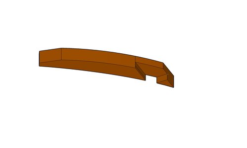
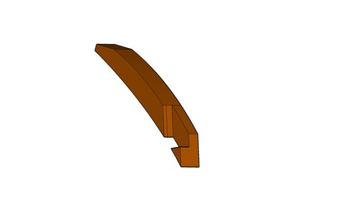
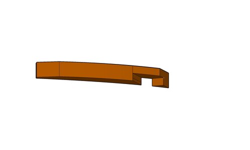
a cross chock is what holds these two floor timbers together and the chock fits into the notch cut into the floor and it will sit on top of the rising wood.

floor8.jpg


the chock itself is a complex shape to 3D model so maybe tonight i will work on that.
 
Interesting chock construction. looking forward to see how you will implement it

this entire stern if you like intericate joinery is a model builders paradise
the boss is making me work out in the shop i hear her now "are you playing around on the computer? better not be!
gota go i will do the chock later tonight
 
this entire stern if you like intericate joinery is a model builders paradise
the boss is making me work out in the shop i hear her now "are you playing around on the computer? better not be!
gota go i will do the chock later tonight
Hmm...Who is the Boss? ;)
 
Hmm...Who is the Boss? ;)

well when it comes to the lumberyard Ev is the boss because she owns the business and i work for her. I am also married to the boss so when i am not at work i am the boss.
humm
a paradox like

if you try to fail and you succeed then which one have you done?
 
Back
Top