Ricerca files dwg

Ciao Morghy
What are the subjects of the drawing(s) you want to find in DWG? I was assuming ships, but you may be thinking of something else altogether.
Allan
 
Ciao ancora
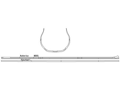
This is getting complicated. There are over 100 frames on most full size ships and about 7 to 9 pieces for each frame. This is a lot of drawings. The false keel is usually made of up four or five pieces so easy enough. Are you look for what is shown below? If so, which ship(s)? Just to be sure, when you say false keels, are you speaking of of the strip on the bottom of the keel? I am guessing you may be looking for something else and it might be a matter of translation and/or terminology. :) Note in the below the false keel can be see on the bottom of the keel from the side and the lowest sketch is the false keel from the top showing the four scarphs which go in a particular direction.
Allan
Keel and frame example.JPG
 
Ciao ancora
This is getting complicated. There are over 100 frames on most full size ships and about 7 to 9 pieces for each frame. This is a lot of drawings. The false keel is usually made of up four or five pieces so easy enough. Are you look for what is shown below? If so, which ship(s)? Just to be sure, when you say false keels, are you speaking of of the strip on the bottom of the keel? I am guessing you may be looking for something else and it might be a matter of translation and/or terminology. :) Note in the below the false keel can be see on the bottom of the keel from the side and the lowest sketch is the false keel from the top showing the four scarphs which go in a particular direction.
Allan
View attachment 450695
Allan wow...
you're at step 3254... and I'm still at step 2... or a little more.
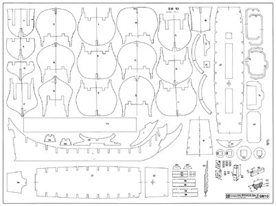
for now I would be satisfied with much simpler drawings like those found online like this one .....

3.jpg
 
As an alternative, in case you are not able to find what you are looking for, you may attempt to re-draw/trace the images you find online in a vector program (Inkscape is a free one, for instance) and export these as either DWG or DXF. The tool learning curve for such use cases is doable, I think for most of us.

Do you need these for laser cutting? Some control programs are taking bitmap images, if I recall things correctly but you might need to clean these up a bit before cutting.
I use Autocad and Photoshop and for better or worse I can do something...
Now I'm determined to create the model of the Chales W. Morgan whaler. In fact I found photos of the kit of this ship in the forum.
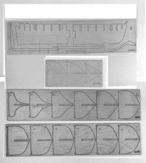
I hate kits, but I butchered the photos to get a design to trace onto the plywood.
So what do I need a file for this ship? .. simple, I use 6mm plywood while the kit uses maybe 4mm.
With photoshop I think I enlarged everything for 6mm plywood.
Of course I also had to correct the perspective and distortion effect caused by the photo. But did I do it right? If I had the cad file instead... it would be very easy to enlarge to my scale... and without errors.

34A2E7A7-A88F-4BF9-90FB-9EA97EADA612.jpeg
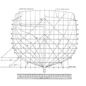
The second option is to transform the various frames starting from this drawing... but my problem is that I haven't yet understood how to create the drawing of a central keel... unfortunately.
But this is part of the modeling game...

morgan_sections_ser100.jpg
 
If you can correct the perspective - although, the images seem to have very low distortion - you should be able to trace them in Inkscape or Adobe Illustrator. From here, having the vector files, you can resize / reposition cutouts as you wish and also resize the whole thing to the scale of your liking.

I don't think any free CAD software can do collision simulation for the parts to really check if the cutout sizes on the keel and ribs are right but this would probably be overkill anyway.

Still learning how to interpret ship drawings myself but, the image you posted could be used for redoing the ribs from scratch but then again you'll need a side view for the keel and the cutout positions.

I'll follow your endeavour with much interest! :)

Cristian
Ciao macika,
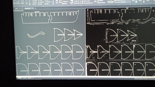
So...(typical Italian interlayer)... with Photoshop I transformed the photos I had posted, then saved them in PDF and imported them into Autocad. Then I went through the drawing with polylines..
So I measured the vertical gaps in the false keel... a bit of calculations and I scaled them in order to have the required 6mm of my plywood... the hull will be 620mm long, which is an acceptable measurement for me.
The next step will be to look for the other details and do the same procedure..

Immagine WhatsApp 2024-06-01 ore 22.52.33_05082d30.jpg
 
Ciao Morghy,

Looks like you have all steps I tried to describe, covered already. It's down to hands-on cutting and assembling now.

You've chosen a beautiful subject, I must say! :)
 
Ciao Macika
in fact after two ... attempts ... to build fantasy models, I understood that the right way is to start from a drawing. Now I have to improve the dwg files. I think I'll split them lengthwise and then double them mirror-wise. At least I will be sure of the symmetry.
Having done this I want to optimize the system of transferring the laser copied drawings directly onto the plywood.
I chose the ship because I don't know how to make lifeboats... on the forum I saw some solutions that I need to study..
In short, the life of model makers is hard and complicated... but with the help of many friends scattered around the world, it can be done.
 
Back
Top