SAINT PHILIPPE 1693 based on the Heller SR 1:92

Joined
Sep 17, 2018
Messages
576
Points
308

Location
Berlin/Germany
Hello,

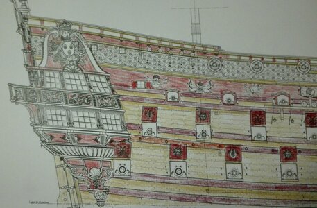
as some of you may know I still have a smaller SAINT PHILIPPE 1693 project and I started his two years ago motivated by the statement of Hubac's Historian (not word by word) "the best you can do to the Heller kit is to rebuild it as a SP based on the Ancre set of plans". So I reprinted all the plans down to 1:92 when figured out the scale given by the hull.

So I have got my smaller project in scale and a ready to run hull ;-) to test out some ideas I do critique on the Lemineur set of plans. Yes I historically dislike his solution for the pair of 24(?) pounders piercing through the transoms lowest floor - changing a given balkony into a wall. But to this point of trouble later more. So my first idea was he needed urgently to come up to 90 guns and so he designd something spectacular carpenters work into the historical proofed artwork of the transom... but I do not believe in his solution. My idea is to add a pair of gunports high above to come two my 90 guns withba pair of light ordonance or to add a third and fourth gun through the bulkhead breakhead as under the transom. So there is a plenty of historical discussion on my way to the SP 1693 that is of outrageous benefit to the 1/64 scratch build. But I will show my motivation later on in detail.
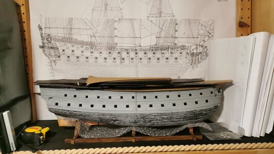
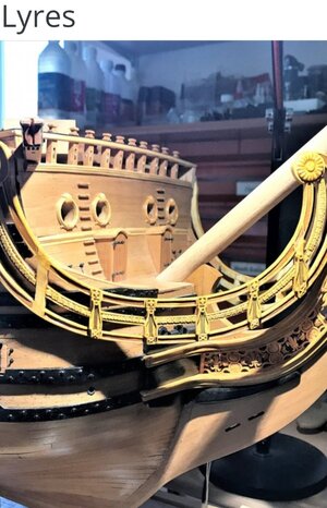
IMG-20210213-WA0022.jpeg
This is the recent situation

So I decided to run into this project - and this is the state of the kit's rebuild recently - but as I tend to overdo it I didnt cut the hull down to the waterline I voted for a hull model.
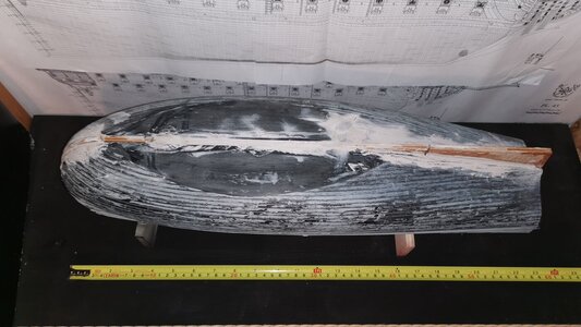
IMG-20210213-WA0007.jpeg
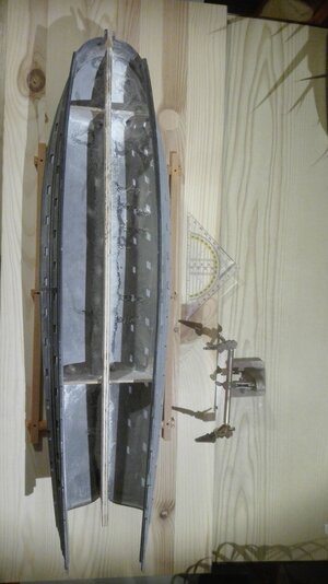
So there was added a 7mm board from straight flat beech plywood between the hull's halfs. This was giving some 644mm to the hull's breadth - some french double foot... The hull is moulded too narrow and too slim in some areas (we will come to this later on). I am very happy haven't decided for the J-shaped additive part I firstly planned with. By adding two halsbulkheads each side The hull got a good stiffnes. The inner corpus was taken by filling the clamped hull by building foam and cutting this into slices.

But the hull couldn't keep it's original keel - as a new one has to be build - so it was cut away and sanded. Then the problem was to glue wood onto plastic without betting the heat of a off going two components glue... I fixed this by mixing deco sand, baking powder and "some pints" of superglue. (A trick I copied and enlaged by sand from an Australian chap he rebuilds damaged Matchbox cars on YouTube.)
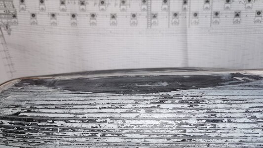
IMG-20210213-WA0008.jpeg
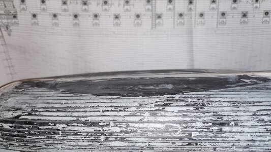
The flat bottom of the hull is really flat - not any plank is engraved with in - due to plastic moulding technology in France half a century ago. This very flat bottom is the reason why no SR builder ever placed the kit over a mirror because for this unplanked uglyness of this "flat" as I call it. But as I decided in a moment of bain damage I want to replank the hull and fix this problem by planking over it cruelly.
So the holes in the keelsom are for the stand as there two covered screwrods will keep the ship's hull upright. These prelonged screws will be running through two baroque angels (moulded from resin) glued back to back as a podestal - some demonic horrifing thought for me as a catholic... But suffers are to be made for the sunking's fleet.
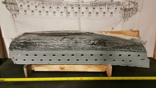
IMG-20210213-WA0005.jpeg
I also builded an "Australian Stand" to work on the hull as I will have to replank it by planks cut from 2mm plastic sheet. And this will be a real main issue as the beautifully made planking advises on the cut throughs in the Ancre planset doesn't match to the Heller hull. So there is a plany of work to be done but as three other SR kits are in my stack I will profit from these experiences very much for ROYAL DAUPHIN 1667 and ROYAL LOUIS 1666. My couch doctor listen to it interested and already gave a key to me for the backdoor of the locked psychiatric ward ;-)
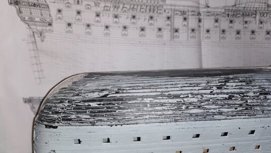
IMG-20210213-WA0011.jpeg
The "flat" is surrounded by a sharp edge and I will have to look carefully to add the bulkhead positions onto the Heller's hull and redo the hull as far as possible. Some problem Marc avoided by building a WLmodel.
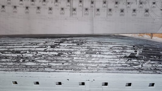
IMG-20210213-WA0010.jpeg
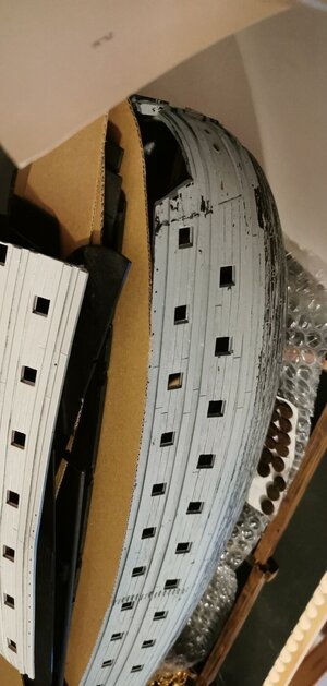
The Planking down here isn't very well done at all due to the problem to get the plastic out of the mould at all. The Heller SR is very much more a solid kit than a capricious model we do long for.
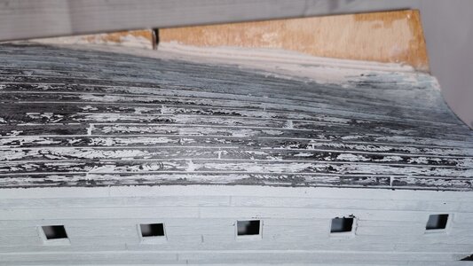
IMG-20210213-WA0009.jpeg
"But await the best is still to come." (F. Schiller, Wallenstein) The deadwood is much too long on the Heller kit. I do suggest building her like this as an RC model will give you the effect of water running through the aft gun ports as the stern didnt have enough buoyancy as there isn't enough hull's displacement. And I also had to cut it away with the keel - this is why I changed my mind and went to a 7mm beech plywood board.

This is the status quo of the project. I do try to find my older pictures for the next article due to the orange stand being mutated into an old oak imitating kind of thing.
 
Last edited:
So the very beginning was the stand casted from shining orange plastic it looks a lot like in a Louis de Funes movie...

IMG-20190807-WA0001.thumb.jpeg.486f587aa22bec37c8b52b5ba444717d.jpeg

So I decided to use several grids of sandpaper and a cutterknife to matten the surface and bring in some grooves and grain.

IMG-20190807-WA0010.thumb.jpeg.c2ff721e8666d06f2490afd316fda035.jpeg

after some days of work I ended with something like this - I called it "orange tree wood" ;-)

IMG-20190809-WA0002.thumb.jpeg.ff5fc49ab9c01113c77b7467c0ba9e01.jpeg

Then I started with a first layer of Revell Aqua Matt 88 using the brush also for giving the surface a further alinement by the bristles in Germany called "Ductus".

IMG-20190810-WA0021.thumb.jpeg.27cbaf61ba2e3294b06ea65018f64344.jpeg

Due to shading the Sandyellow 88 I was able to seperate the imitated pices of wood and looking at it I exacly know I learned this technic on paining half timbered houses for 28mm tabletop surplusses.The wedge doesn't work out as I liked it to be - but I decided not to run crazy on this minimal grain and to accept the given output. Nearly all these colour shades have been used for my CSA infantymen years before so I now realize by this example to reuse the lessons learnd in tabletop modelling and railway modelling.

IMG-20190810-WA0024.thumb.jpeg.302800d26a784cdccdd52cefef819ee1.jpeg

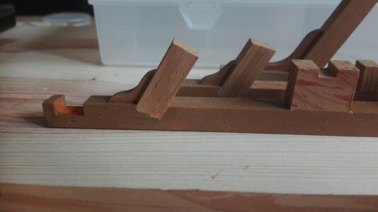
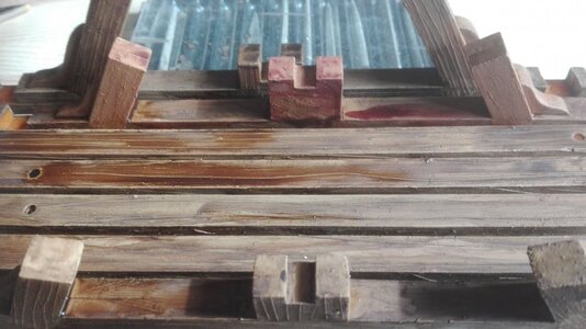
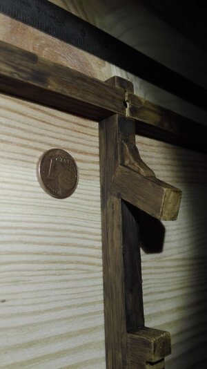
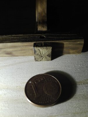
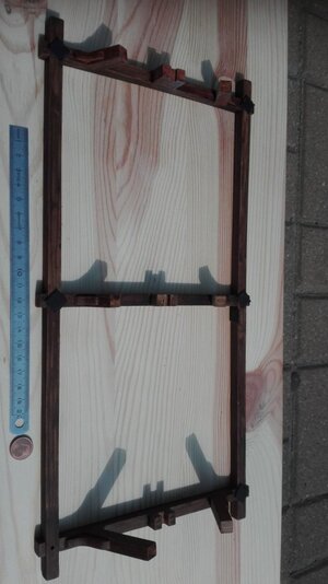
The central support for the keel was a real challange due to its simply made shape I took - next time I would use some elaborated for the joins as a "dovetail joiner" - I couldnt figure out the proper English vocabulary - kind of a wedge-like joining.

IMG-20190810-WA0026.thumb.jpeg.34b75349c32dd07d0fd78b9c6b99afb8.jpeg

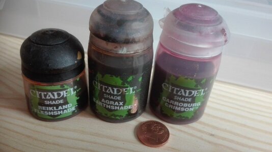
These three inks and sepia were used as washes to darken the surfaceinto an old oak dry wooden image.IMG-20190810-WA0033.thumb.jpeg.e6b7c138ad11355cc40a23785efe2c6f.jpeg

The two parts of the imitated wood were seperatly treated by layers of the ink in differend sequenze (earthshade, earthshade, crimson vs. crimson, fleshshade, sepia)

IMG-20190810-WA0037.thumb.jpeg.a35107da989582d95c6717134ca47cb5.jpeg
...and due to this I started to catch the effect I was after layer by layer

IMG-20190810-WA0031.thumb.jpeg.6e5a031afe7bce3ebaeffc910a50ad45.jpeg
- it is not a job to hurry within. any layer must be dry before the next is added to avoid arubbing away of the lower layer by the next one.

IMG-20190812-WA0027.thumb.jpeg.ab37b7052f59eda3c95a94058ee3f84a.jpeg

And by slimnking foreward layer by layer

15656440796181991982167.thumb.jpg.462f94574d34fd13fcf76806cf59ac64.jpg

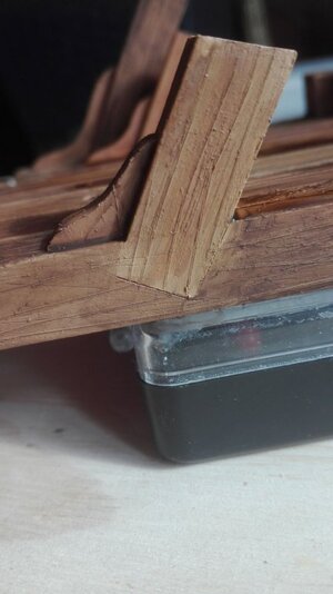
I came to this result I was realy after...

IMG-20190824-WA0006.thumb.jpeg.053e35692c1f6cc232a5fd75cada286d.jpeg
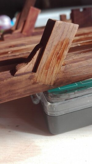
And as happy to say the joints aren't really recognable.

15655335802901098645849.thumb.jpg.770f7f2fc9cecb6e600d752eba516104.jpg
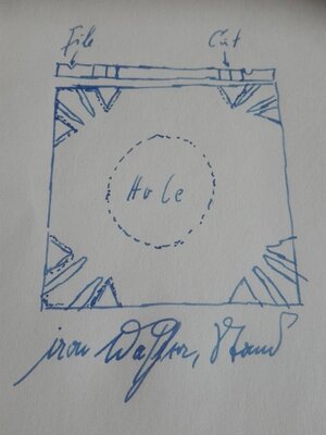
So I added a doodling in my scetchbook on the way to work on train and was able not to forget about it in the evening,

IMG-20190813-WA0002.thumb.jpeg.ecc5c290dee6955d53880d9bf60880ba.jpeg

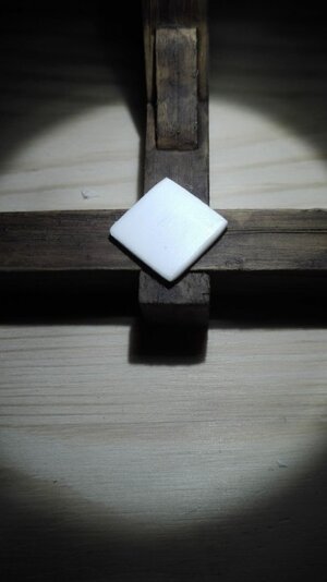
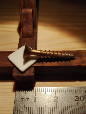
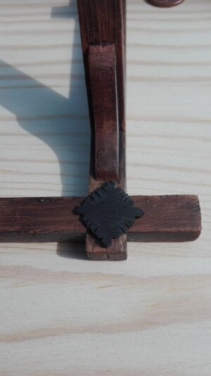
Due to avoid any viewable gaps I decided to invent baroque washers

1565647647428-1278723451.thumb.jpg.102cee1dd700442bad6645c884ecbad8.jpg

to cover the sunk in heads of the modern screws to fix the stand onto the board.
This board does fit exactly into my shelf system by these unknown Swedish compay.

IMG-20190813-WA0007.thumb.jpeg.46973d6f964a5638754f03a82a3d7e16.jpeg

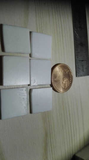
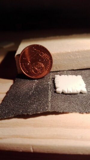
Cut from a pice of 1mm plastic card.

IMG-20190813-WA0011.thumb.jpeg.ab8a6911c93a896aca377163c8ab5d42.jpeg

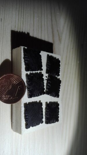
Afterwards using a needle file to cut in the groove's pattern

IMG-20190813-WA0013.thumb.jpeg.6f630c049877c3c0e9c71841f7c784f6.jpeg

Spraying the sextett in a mattish black

IMG-20190824-WA0023.thumb.jpeg.36105c89bc8d30ce080177b72a71360a.jpeg

test fitting still was suifficient.

IMG-20200228-WA0047.thumb.jpeg.06fc5dbef5b4fbc4b4e0065c2b531558.jpeg

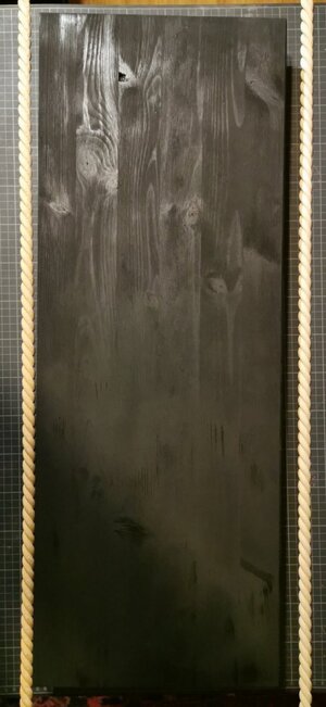
Giving the board a good layer of matt black, too and a deorational wooden rope.

This was all work of last year and it still isn't ready the four sided nuts are still in development.
But I do hope the progress will come after my removal. So this was the stand...
 
The main problem is that the SR hull isn't the SP's.

IMG-20190430-WA0074.thumb.jpeg.44b67f120a93e0ef9dc7a90bd4ebd1d7.jpeg

So often the fitting between the widened hull an the drawing is quite good and sometimes yiou do feel miserable.

1557044252240-841480384.thumb.jpg.752a40367ebc41bbc1be6843b568ac76.jpg

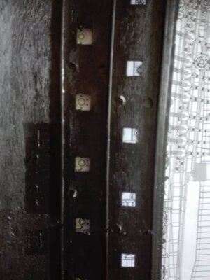
The gunports do hardly show any variation

15570445155501643713264.thumb.jpg.b9540d2a100d369d1dbe0dc0a14048f8.jpg
but looking closly some misalignment is obvious not being a CAD guy I will have to go it the hard way by a recangular pattern and correcting grit by grit...

Or keeing it as it is and do belive in the fact that I avoided damaging the hull. But the run of the wales differs from the SP's run and so on - so the differences did pile and I decided to go the hard way and I must di the measuring grit I learned by archeologists (just turning it upwards).

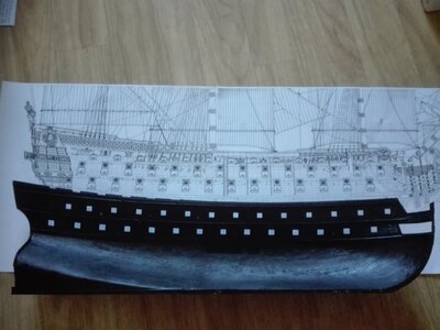
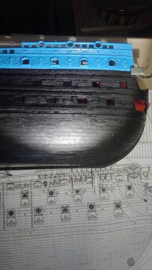
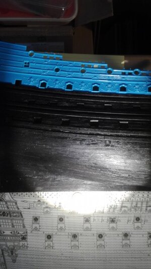
Now a row of three pictures comparing hull with UD section added (in light blue)

IMG-20190504-WA0040.thumb.jpeg.05c7fe99a74a70fb10d3b5f0c2cb8187.jpeg

to the most detailled view of the hull (Pl.45) scaled down to 1:92 so we can compare

IMG-20190504-WA0041.thumb.jpeg.e231436bf2436af07c612ef9fa82aba8.jpeg

so we can see the effect what has tio be chanced and more ande more differences does appear.

IMG-20190504-WA0042.thumb.jpeg.ce0776e8692347e020d138b2a4e21bad.jpeg

and I feel forced by Heller to manipulate more to the hull as I thought I would do
even now one year later I still feel the troubles staring down towards me.

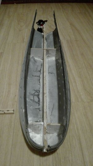
As I told you I glued togerter Hulls halfs and centerboard by trhe three component mixture
of sand/baking powder/superglue.
IMG-20190427-WA0029.thumb.jpeg.6b64b41bfc9f57e419f06c6a125877af.jpeg
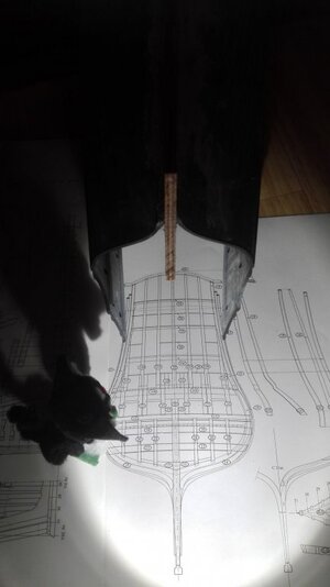
here a topview down into the hull showing what it really does look like:
Looking so rude but being so solid as concret.
 
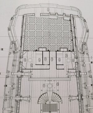
So let's walk into the less practical place and look on the questionale reconstruction of the transom by Mr. Lemineur:

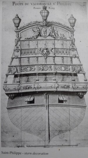
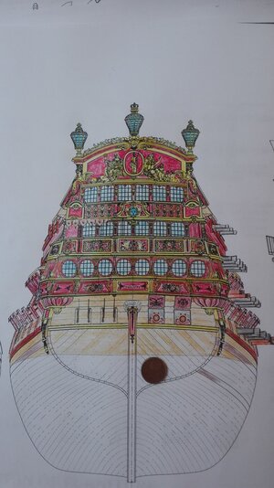
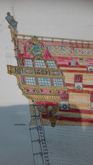
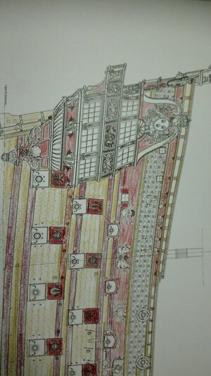
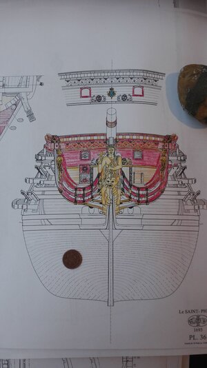
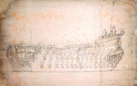
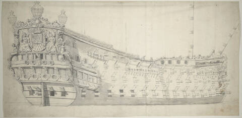
, What I am talking about is the rude changing from a historically given document from 1692 pattern of

IMG-20190817-WA0034.jpeg
IMG-20190817-WA0036.jpeg
Couronnament
Row of windows
Row of windows
Loggia (set back inner wall)
a pair of gunports* *The side view doesn't fit to the stern view due to the drawn out balkony not being mentioned in it's sister drawing.

to a
IMG-20190817-WA0019.jpeg
IMG-20190816-WA0007.jpeg
Couronnament
Row of windows
Balcony
Row of windows
Two pairs of gunports

due to add two gunports in the lowest floor to come up to these 90-gun ship the SP1693 is called.

So what do we get by this addition of two integrated gunports are
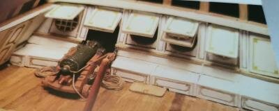
- an intersting and complex pair of features to ran out the guns in an officer's accomodation
- a pair of opening in the accomodation weakening the even fragile transom further on
- a pair of openings in the transom not able the keep wind and cold outside


f165t125p191947n2_FmTyebOU.jpg

So suddenlx with the urgent need to cover the windows by lids not to break the glass by the force of the black powders air pressure from insidewhen guns on cariages roll back.

IMG-20190818-WA0007.jpeg
And with some unsufficient timberwork not really able to take the force of a 24pounder's recoil I do suggest.

So what I do think is the important question Why not staying with the original transom an searching for opportunities where to add those two guns?

IMG-20190816-WA0003.jpeg
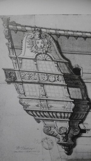
One possibility is to a a fourth round gunport sternside to add a very light gun (as I didn't have my books ahand I can't say how many guns of what type of ordonance were aboard.) But nothing is recognable on the original drawing of the side gallery.

IMG-20190817-WA0021.jpeg
So if it must be a pair of guns of the medium calibre (due to the number of guns innthe MD) the gunports may look
astem. So further two ordonances piercing through the breakhead bulkhead with six instead of four barrels. Why not if no obstackels (sails, rigg, yards) of the bowsprit's rigg will be hit? Or is this weakening the breakhead bulkhead too much? (I found some evidence the French baroque ships had had round gunports afront leaving very little space between ordonance and framing to let in seawater overcoming freshly from the toilet).So does this looks like a not too stupid escape?

So as there is no front view coming to us it looks like the best way to solve the problem not to build an eighteight gun ship. So here I do earn a lot of information for the 1:64 project.
What does our specialist do say?
 
Last edited:
Thanks Ziggy,
I appreciate that very much but must say there will be a gap due to my removal* in march. This change in my live was sudden and unplanned. "Do tell god your plans and listen to his laughter" ,is a wellknown saying in Germany. So the project will be transfered and being my only project I can deal with as it is very handy. So I will mainly plan, doodle and draw untill summer to get rid of the 89th and 90th gun problem on the one hand and starting to work on a measuring grit to get Heller's hull and Lemineur's drawing together.

IMG-20200228-WA0093.jpeg
Do you have any advice for how to deal with the "edge"! Here between flat and hullside - here highlighted in yellow on the upper side.

IMG-20210213-WA0008.jpeg
But how to solve this serious problem on the kit? Not only by planking 2mm thick plastic planks straight over it... it will end with a bad unnatural looking kink in the planks, isn't it? Got no spankling idea at the moment and I am till 11 month feeling completly uncomfortable with this flat and sudden start of the hullside... and I know that this is an important and obvious design feature anybody will look for as it makes the hull looking Frenchier... so your ideas are highly appreciated! Any guess is wellcomed warmly.

I pushed this project into the shelf due to this problem and some others I couldn't solve till now. Instead of working onto these obstacels I tryed to work around so this is the project to concentrate all my knowledge and idealism into for the next years.


____________
*So I will have to carry nearly 100,000 books right through eastern Berlin further eastern, together with a shipyard's set of wood, drawing material, rolled plans, bandsaw, table saw, scroll saw, disk sander and colours, drawing tools. There were some antique furniture several big plants a and my rest of stuff like a 1:150 PREUSSEN, three SR, as several dozens of wooden and plastic kits. Very complicated to move a set of venus flytraps in a swamp from destilled water and peat in windowbox wet and heavy.

IMG-20200308-WA0010.jpeg
And delicte to transport a record steamer project of 1902 to keep the Blue Ribbon Band in German hand for further ten years.
IMG-20200308-WA0006.jpeg
A five funnel ship projectioned by Prof. Schuette for the North German Lloyd in 1:350.
IMG-20200308-WA0012.jpeg
This liner had to have retracted hull sides to get enough ligh into the hull - noticeable by the pumped water on the hull. Otherwise nobody would have remaked this feature of a kink along nearly the hole hull.
So these really complex objects do have to been removed into the new flat - with a little carpet of a garden.

But I will leave my 14 squaremeter hobby room to enter a nearly 40 squaremeter ship yard with a solid old wooden workbench. Sorry for this but I made a 179° change in my live... called something like "LIVE 2.0"
 
Last edited:
GUNS N° 89 AND 90

As I am doubtful about the Lemineur construction of two gunports into the row of windows in the transom - mainly due to the forces of recoil onto the light structure behind the the transom. And sencondly due to the moisten and wind comming in the officer's accommodation due to gaps arround these lids

So I decided to do a walk around and try out where elese these last two guns could have been placed.

There is in the booklet of SAINT PHILIPPE no spreadsheet about the ordonances grouping after pounding. So I can add a pair of barrels to the light as to the medium ordonance.

I. POOPDECK
Butto start with the less historical solution I think about to add the pair of barrels to the UD on the poop. As the side view doesn't have a fourth ring round gunport it is highly questionable but will satisfy any barrel counting child infront of the show case.

Polish_20210216_011842180.jpg
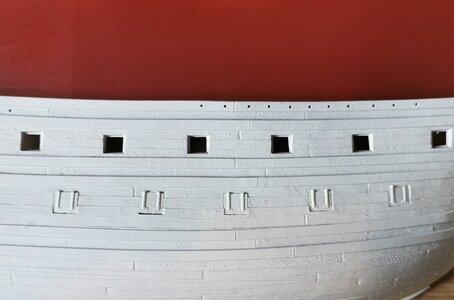
Here I simply added a copy of the other gun ports into the estimated place.It is a much more discreet way to add a pair of ports into the hull than by cutting an integrated gunport into the transom forcing you to alter the hole construction. I have to admit misplaced it a bit towards stem in these smartphone picture manipulating app but please take it as a coloured scetch.
But I must remember it is in opposition to the original sideview from 1692 so it is my line of retreat.


II. BREAKHEAD BULKHEAD
As we donat have any historical drawing of the breakhead bulkhead I am free to place the two guns in the breakhead bulkhead as just a second pair of gunports to the front.

Duing this I will have to removel the stairs a bit or double it.

By this I do eleminate these questionable solution in the transom turning it 180°. So there were some historical examples of breakhead bulkhead with four gunports in the UD. Keeping the other two in the MD we will have a proper solition with a real heavy armament to the front.

Polish_20210216_010131398.jpg
Here it looks reasonable but if we follow the question "Could this really have worked?" as I like to ask.

Polish_20210216_010201789.jpg
So here are these troubles I do run into:
There is the catheads ends that would stop the recoiling gun's carriage and turning it's way towards the centerline. As we have no evidence about the breakhead bulkhead's shape this doesn't collidate with the sideview of SP but I think it has to a an acceptable solution to the problem we do face at this 90-gun ship.

What do you think about this way to get rid of the transom's questionable armament?
 
Last edited:
As Marc pointed out the false winfows may be pannels being removable the 89th and 90th gun may just fire through the toilett door.


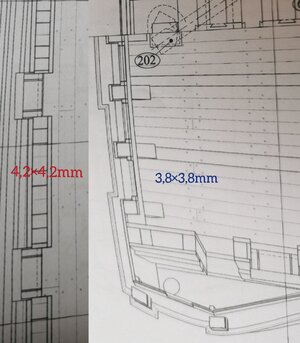
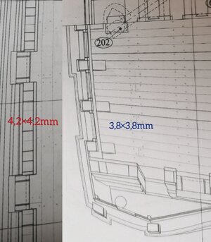
And it is the as I thought the transom timbers are weaker than the frames. In numbers we e are at 4,2×4,2 mm = 17,64 sqmms

vs. 3,8×3,8mm = 14,44 sqmms. What to do with this information? So if 17,64 is the regular number used to vatching the guns recoilment force regulary than 14,44 can be sufficient to be used? But what do you think about these numbers? Has Lemineur quit his complex conszruction in the next edition?


I pictured both parts and added them side by side in scale to show the difference.

Polish_20210216_155720162.jpg


But if we take your idea the gun to pointing through the officers toilet - that sounds like a great idea. So I will move the door to stem as the gun crew would have to avoid hitting the stanchion directly infront of it's gun's muzzle. All we have to change is the hight of the window sill - or the hight of the wall inddr the window's pannel getting them in line to the gunports underside.

But all in all it is an interesting and plausible and resonable idea...


I will keep this in mind my only question is where wrre the 24pdr guns stored in between?...not to annoying the officer's beloved shining wooden parquet?

I will copy athe crucial part of the 1/64 plan again cut out the gun and try it out - where to place it.


b. t. w. there is no toilet seat in the "chamber of relieve"...
 
Here again a critical look at the flat of the SOLEIL ROYAL from Heller and a comparison with a scaled frame drawing for all those who would like to dare to venture into this break.


At the moment there is an ambitious conversion project to a historic SR in the USA by Marc and a newly started SR by Steve from Downunder I will watch carefully to learn from. So again a model maker is taking up this historically correct path and has announced that it will no longer color its SR in blue either. World is sometimes also changing from the better to the best.

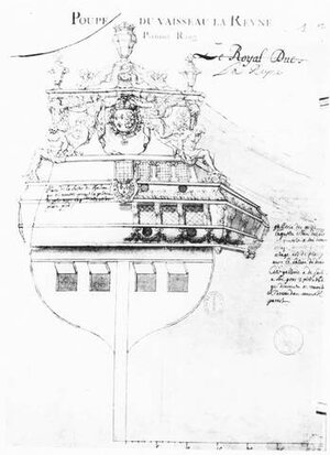
Our Belgian Cederyc who rebuilt it to

reyne_10.jpg
LA REYNE from 1671

la_rey10.jpg
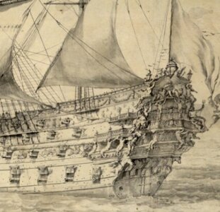
based on these two vdV ink&wash drawings

reyne_11.jpg
showing her as the very link of leaving the Dutch way of decoration into the italien style free standing sculptured figures fromnpoplar right into the French way of life and bringing a "kind of armed shoe box"* into our mind... slowly making progress because of the relocation of the building's own wales being a big obstacle for progress at the hull.


An just me, the German who wants to cover the hull of the SAINT PHILIPPE 1693 with a completely white hull without detached wales and with a vermillion red Upper Deck's friese of decor adding heradic symbolic batches on top of the MD and above a lattice grit with fleur de lyse in it. I have to remember tat the (even lightened mit yellow ocker red wa stiil darkened by the linseed oil).

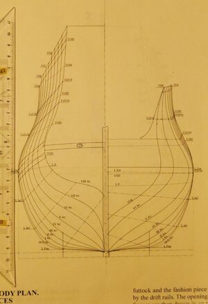
Polish_20210217_000505347.jpg
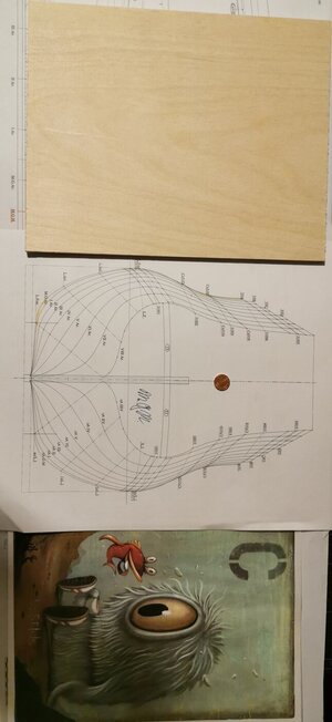
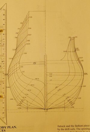
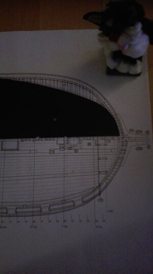
I added a triangle ruler to the lines plan to give you some impression of the size of the project. So you can see the 10 is at the keel's underside and rising up to 208mm hight at the hull's side towards the hutt deck over poop. L. F. is the bent CWL so we do look onto the horizontal keel.


Polish_20210217_092444759.jpg
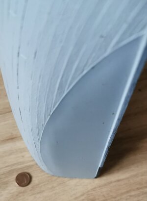
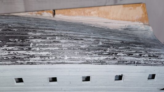
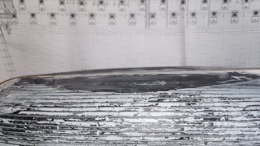
and a picture of the flat to show how much changes have to be made with this kit's underwater part.

Polish_20210217_092616410.jpg
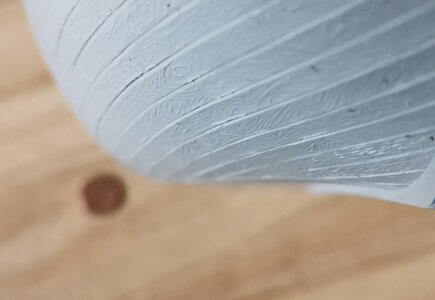
I am not happy with the shape recently and have to get rid of this line coming out - by sanding...

... but what stays is this very sharp edge in the kit's surface form the planked towards the smooth surface that runs me mad till I got a first look onto the hull of the kit when opening this fantasticly large box.

Polish_20210217_124025603.jpg
Here the testpice simply rough and quick can sprayed white and the other part red with a simple pice of card board added to give you some idea if the coulouring I am aiming for in particular without any CWL.

The Vermillion Red, the Lapislazuli Blue and the Lead White and I think some verdisgrin green will find atheir own recovery by trying to replay their manifestation and their behavior in comibation with naturally pressed linseed oil on oak and poplar to get the best hidtorically correct assumptions for their way catching our eyes.

Edit:
Ohhh no I didn't run mad and worked with a dwarf's axe on the kit this is a kit pice I got sent by Mark for shape and testing purposes. I do appreciate it very very much and do think it will be very helpful with the first testplankings and adding a right joint to the surface of the wales hidding the villainous join to the public eye.

P. S. As I am starting my removal I am going to enclose the ship yard for some weeks only being able to deal with some boring things like literature and working on copies to try out some idea at the plan. The only nice thing is that any progress run into both scales and all Heller SR based projects. So I will try to definitely pointout were to place the lines of the SAINT PHILIPPE 1693 plan onto the Heller hull &c.

*Children do drive honestly the truth to us.
 
Last edited:
Hello,
today I had a phonecall with MrKremer, Dr rer. nat. from Kremer Pigmente. And he told me our French baroque red wasn't vermillion as I estimated by me an Lemineur noted innthe SP 1693 booklet...

Red_lead.jpg

I have been told vermillion would be much to expensive as a ships hull is about a sqsuremile to paint.

images (2).png
it was the much cheaper and longer holding MINIUM or Lead(II,IV) oxide.
And it can be added with an ockre yellow to get it to some kind of lighter orange. But we have to keep in mind these colours are all mixed with leenoil on oak.
The second depression was it is not lapislazuli that was used not even for St. Mary's coat - it allways was Azurite. As it is a blue stone being much cheaper than the imported from Afghanistan Lapislazuli.

So I ordered little ammounts of Azurite, a powder adapting the very effects of leadwhite without beings such poisoning.

Verdigis for the floral effects. So I have the job to try these original colours out on oak.

And a black for the mixtoures.

Dr. Kremer told me the tar from below does work through the lead white and any other colours. It is a pitty but as the plane modellers spray all of their joints dark grey we would have to do, too, as the tar is been soaked in any colour from below. What a pitty only freshly painted ships seem to have been free of these stripes.

Dr Kremer does sell pigments to artist and restaurateurs d'art all over the world and is also in contact to several owners of antique ships that do purchase their original colouring at his store. He was very kind and helpfull.

What do you think about this change?

P. S. :


Due to the highly viewable nails (RK1668) Polish_20210218_102615289.jpgin my e-mail I ordered additivly black powder for on iron.

And he told me the figures were painted naurally in skin colour and gold and shadowed (like a wash) to give them much more deepness.

The third depression was that the figures are perspectivilly longered and shortened towards the usual point of view of a visitor - as mainly from the waterline to above. So I do decide against this "deformation progress" my viewers do stand directly vis-a- vis the model... but historically it is a fraud. Still struggling against myself...
 
Last edited:
Thanks Brian, this is very kind of you.

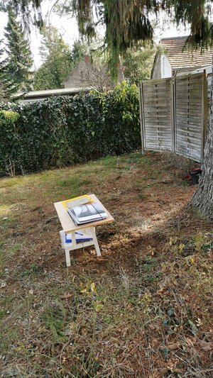
I have decided not to fix the stand onto the black board due to the risk of crashing it within the transport. There will be two new shipyards a longer clean one innthe flat and a second one down in the cellar with disk sander and table saw.
The "cleanroom" has got carpeting and I still have got an idea there is a carpet monster within...*
So I will build a kind of workplace for the cutting of planks out of cardboard and plastic sheets to trying to minimize the trash I do produce. It is obvious that "cutting some planks" will be the main job of the build for the next months I bought my first own hinged lid bin for these purposes.
The sanding of the modelship would be the next step to went to untill I got this aware of :
signal-2021-02-18-092349.jpg

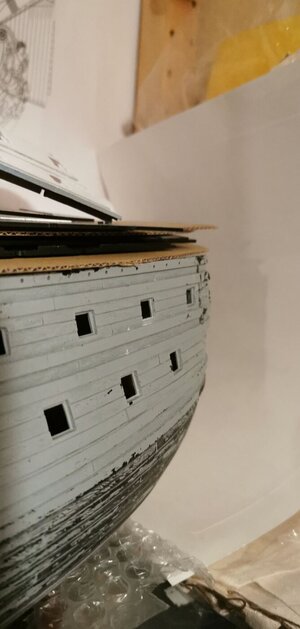
The hull is sinking in (as we do know now from this picture)
IMG-20190724-WA0010.jpeg

here the decks outline is compared to the plan and they nade a short cut.

IMG-20190806-WA0003.jpeg
Here in the topview the difference to a normal baroque ship gets obviously. To be honest I am still stuggeling to my self.
If I sould add a bearing in here to repair the kit but I Think the white will hide a lot

signal-2021-02-18-092409.jpg
I wasn't able to catch the effect from my whitened testbody.

But I am afraid this won't last for long - until the minium red comes in and this harsh and biting line will make it suddelny much more obviously.

A question to those that biult the kit -> May this ruin the hole kit?

(I am sitting between more&more removalboxes and less&less filled shelfs I still keep the pick of my baroque naval literature special).

*but this room will be given to a forster child so the room isn't for me alone for very long.
 
Hello,

as some of you may know I still have a smaller SAINT PHILIPPE 1693 project and I started his two years ago motivated by the statement of Hubac's Historian (not word by word) "the best you can do to the Heller kit is to rebuild it as a SP based on the Ancre set of plans". So I reprinted all the plans down to 1:92 when figured out the scale given by the hull.

So I have got my smaller project in scale and a ready to run hull ;-) to test out some ideas I do critique on the Lemineur set of plans. Yes I historically dislike his solution for the pair of 24(?) pounders piercing through the transoms lowest floor - changing a given balkony into a wall. But to this point of trouble later more. So my first idea was he needed urgently to come up to 90 guns and so he designd something spectacular carpenters work into the historical proofed artwork of the transom... but I do not believe in his solution. My idea is to add a pair of gunports high above to come two my 90 guns withba pair of light ordonance or to add a third and fourth gun through the bulkhead breakhead as under the transom. So there is a plenty of historical discussion on my way to the SP 1693 that is of outrageous benefit to the 1/64 scratch build. But I will show my motivation later on in detail.

View attachment 213260
This is the recent situation

So I decided to run into this project - and this is the state of the kit's rebuild recently - but as I tend to overdo it I didnt cut the hull down to the waterline I voted for a hull model.

View attachment 213265
So there was added a 7mm board from straight flat beech plywood between the hull's halfs. This was giving some 644mm to the hull's breadth - some french double foot... The hull is moulded too narrow and too slim in some areas (we will come to this later on). I am very happy haven't decided for the J-shaped additive part I firstly planned with. By adding two halsbulkheads each side The hull got a good stiffnes. The inner corpus was taken by filling the clamped hull by building foam and cutting this into slices.

But the hull couldn't keep it's original keel - as a new one has to be build - so it was cut away and sanded. Then the problem was to glue wood onto plastic without betting the heat of a off going two components glue... I fixed this by mixing deco sand, baking powder and "some pints" of superglue. (A trick I copied and enlaged by sand from an Australian chap he rebuilds damaged Matchbox cars on YouTube.)

View attachment 213264
The flat bottom of the hull is really flat - not any plank is engraved with in - due to plastic moulding technology in France half a century ago. This very flat bottom is the reason why no SR builder ever placed the kit over a mirror because for this unplanked uglyness of this "flat" as I call it. But as I decided in a moment of bain damage I want to replank the hull and fix this problem by planking over it cruelly.
So the holes in the keelsom are for the stand as there two covered screwrods will keep the ship's hull upright. These prelonged screws will be running through two baroque angels (moulded from resin) glued back to back as a podestal - some demonic horrifing thought for me as a catholic... But suffers are to be made for the sunking's fleet.

View attachment 213267
I also builded an "Australian Stand" to work on the hull as I will have to replank it by planks cut from 2mm plastic sheet. And this will be a real main issue as the beautifully made planking advises on the cut throughs in the Ancre planset doesn't match to the Heller hull. So there is a plany of work to be done but as three other SR kits are in my stack I will profit from these experiences very much for ROYAL DAUPHIN 1667 and ROYAL LOUIS 1666. My couch doctor listen to it interested and already gave a key to me for the backdoor of the locked psychiatric ward ;-)

View attachment 213261
The "flat" is surrounded by a sharp edge and I will have to look carefully to add the bulkhead positions onto the Heller's hull and redo the hull as far as possible. Some problem Marc avoided by building a WLmodel.

View attachment 213262
The Planking down here isn't very well done at all due to the problem to get the plastic out of the mould at all. The Heller SR is very much more a solid kit than a capricious model we do long for.

View attachment 213263
"But await the best is still to come." (F. Schiller, Wallenstein) The deadwood is much too long on the Heller kit. I do suggest building her like this as an RC model will give you the effect of water running through the aft gun ports as the stern didnt have enough buoyancy as there isn't enough hull's displacement. And I also had to cut it away with the keel - this is why I changed my mind and went to a 7mm beech plywood board.

This is the status quo of the project. I do try to find my older pictures for the next article due to the orange stand being mutated into an old oak imitating kind of thing.
Hallo Chris alias @Iterum
we wish you all the BEST and a HAPPY BIRTHDAY
Birthday-Cake
 
Hello friends!

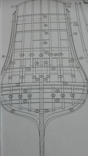
Now all the papers rolled plans and the stand are in the new flat and my hull also. Tomorrow I will rework on the plans to come again into the project. The first step will be to rework the Lower Deck (LD) to get the hole hull stiffer for the planking I suggest at the moment.

Polish_20210225_000713184.jpg


But first thinks first! The deck will minimize my finger's space to work in the hull! So first the gunports than the decks. And that chonology seems to be more right. A single pint of planing vanishes a tanker load full of avoidable problems.

THE GUNPORTS:


Polish_20210216_155720162.jpg

There is clear evidence from the pictures that the inner frame of the gunport could allways be seen. In German we call it Trempelrahmen... I have to leaf through the monography to find the correct English termicus technicus. Sorry for this.


My second step will be to give the hull more deepness at the gunport frames some 4,2mm for the frame and 0,5mm for the inner planking is measured.


FB_IMG_1614246437945.jpg

I HAVE TO REMEMBER THIS IS THE ONMY REASONABLE OPPORTUNITY TO MOVE THE MISPLACED GUNPORTS!!! SO I AM INURGENT NEED FOR A 100% SAFE MEASURING STAND THE HULL CANNOT SWITCH AWAY.

Do you think this is enough? So this will be the next job imitating the gunports inside. What does the frame around the gunport look like? What joints are obvious and must be shown?


THE DECK:

The third step must be the painting of the deck's surface in Revell Aqua 88 matt... but still thinking about the joints of the planks and if the thicker bars between must be darker as they were from oak instead of marple or some softwood? Edit: I really do think about trying out the method for the stand on the planking of the LD to get a feeling for the work and I can copy the planks rightbfrom. the plan... "Sadly nothing will be seen of this work." some of you may say... I do think its the right place to hide my trial-and-error-elaborate: Deeeeeep in the hull. (The Orlopdeck might be the better place.)


FIGHTING THE FLAT:

Polish_20210217_092444759.jpg
On the testing hull Marc sent me the borderline of the Flat (what is the right termicus technicus here?) is very obvious.

Before my first sanding of the hull this surrounding line (and the much too low placed waterline) casted onto the planking in typical 70th manner disappeared first. I got rid of them both with a greshly opened scaplell. Than ut is time to mark the bulkheads onto the hull and figure out where to place the bulkheads. And I do think I do not do this 89,1° from the PLAN N° 1- or is this completly wrong?

But the beech plywood is in my personal opinion not fine enough to take this job.

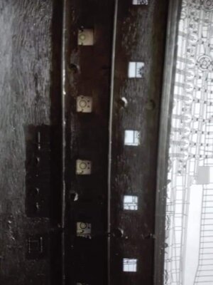
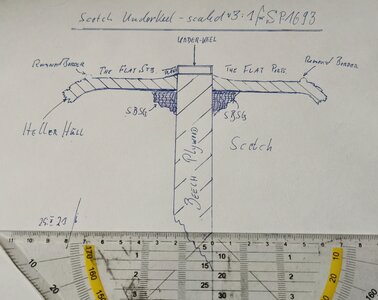
Polish_20210225_093040320.jpg
So I do have to fix a "under-keel" of 7×2mms from. plastic to scribe the lines onto so I am quite prepared to set the cutoffs of the lines plan onto he hull


IMG-20210213-WA0009.jpeg
to look in the first place for the right filling blocks at the deadwood to get it from a Heller shape into a SAINT PHILIPPE one.


Polish_20210217_000505347.jpg
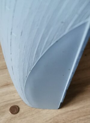
The secons critical point is the very sharp turn of nearly 110° from the Flat into the Underwater Hullside at midship.

To get the hull with its "rounded edge" on the border towards the Flat into a

IMG-20210213-WA0008.jpeg


mostly correct shape without sanding a hole into the hull...

1f914.png
 
Last edited:
Back
Top