Santisima Trinidad OcCre kit #15800 build from 2004 to 2012

Joined
Aug 16, 2019
Messages
870
Points
343

Santisima Trinidad OcCre kit #15800 build from 2004 to 2012

For the one that have kid
If you have read my post on the Hermione you know that it was build for my younger son that want one because is older brother got one.
What happen is this, when the older saw the ship he was not happy because as he said he got a small fishing boat and is brother a war ship with gun.
I know my boy so I told him to buy himself a model and I will build it, but knowing the boy I specified NOT A 3 DECKER the devil found the only 4 decker to ever have existed the Santisima Trinidad and I was stuck to build it. And of course to out play his brother he got the section and the captain launch.
So here are my adventure

The box is big and the content is
6 scale drawings
1 instruction booklet and
1 Color booklet in color with photo for each step
The wood is well package and all the small part are in plastic box.

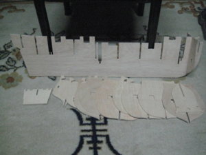
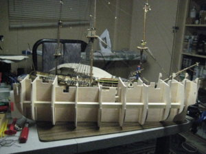
the installation of the frame
the installation of the battens and small interior deck
the pose of the 2 crossbeam that will give the structure the rigidity necessary to the kit

All those step are done in a plywood of good quality of 4.5mm thicknes

2004 is the step I was at that moment but I will not work very much on the structure for now as I will build part on my cross section that are similar to the ship so in place of having to repeat the same part in the future I will make them in the same time as the one of the section.

There are 3 Santisima Trinidad
The OcCre version the (Altaya) version (I think not available anymore)
And DeAgostini still available for 899 British pound or 33 mounts at 30 British pound per mount (September 2018)
Altaya came in publication similar to what Hachette do weekly instalment a few part at the time the only difference between the 2 kit is mainly the hull frame
1a.jpg1-3.jpg

1-5.jpg
 
It will be a bit mix up as I was doing the section in the same time

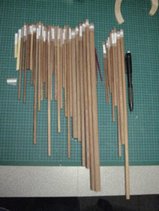
When preparing the lower main mast and the spar for the section I did my spread sheet for the ship and cut all of them for both kit in the same time with tag to identified them.
I can’t emphasise enough the need to prepare and plan in advance your cut for any build that you doIMG_2686.jpg
So here are all the mast, yard and spar for both kit all cut and tag ready to be form properly.
 
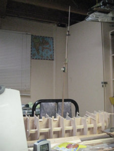
As I finish the main mast for the section I install also the one that go on the ship to have an Idea of the high. Well it is high it will be a huge ship. At this point all the yard are ready to be prepare and install for the main mast.
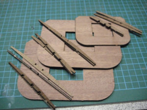
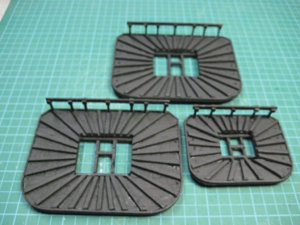
On the Santisima you have 3 fighting platform they are similar to the one that go on the section photo 3-2 so I decide to build all 3 of them not only the one that go on the main mast and I replace the plywood and modified a bit the construction.
Photo 3-3 before painting
Photo 3-4 all 3 platform build I will put aside the one that will be use later it was easier to build all 3 platform in one shot
3-1.jpg3-2.jpg3-4.jpg
 
This step is the planking of the waist deck a very short waist deck if you compare it to the Domus Altaya publication (Fam/Andrea ST) version.
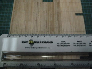
The planking is done with 3mmx1mm plank
A word of caution here the plank that is supplied where cut a bit unequal resulting in little problem of adjustment.
I use the overlap method for the middle photo 4-1 and as you see the result is nice photo 4-2
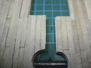
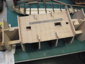
The deck will have a width of 13cm as per photo 4-3
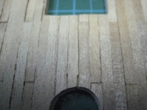
The deck is complete I install it but it is not glue yet photo 4-4 as I have a few thing that have to be check before I go further
4-1.jpg4-2.jpg4-3.jpg4-4.jpg
 
I have installed the waist deck temporary photo 5-1 and mount all the plywood sheet that will be the base of the structure and give the position for all the gun port photo 5-2.
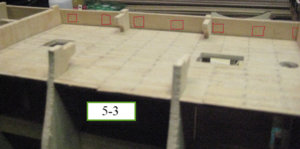
The reason for that it is that I want to see in advance what kind of problem I will encounter when I go further in the build and for good reason photo 5-3 show the bulkhead and the gun port that I have circle in red as you can see one of them will be tight as I have the intention to put gun there because they will be visible. But because of their position I will not have to make a complete rigging of them a partial one will be sufficient.
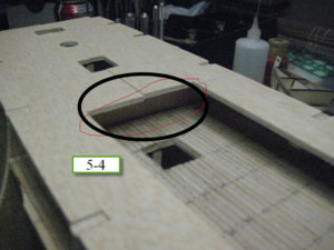
Photo 5-4 show you the forth deck frame that I have position temporary now toward the stern the wall that serve for support for the deck is clearly visible so that something that I will have to fix before doing the deck photo 5-4
That operation will have for consequence that a floor will have to be build that must be extended up to the stair well. Another surprise was the height between the 2 floor compare to the section. on the section I have a height of 24mm but on the ship only 16mm that is a surprise as both model are from the same builder.
1a.jpg1b.jpg1c.jpg1d.jpg
 
Fixing what I did not like on the previous post

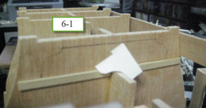
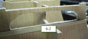
I have made a form and with my Dermel open the bulkhead 6-1 6-2
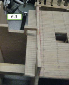
6-3 extended a bit the floor of the deck
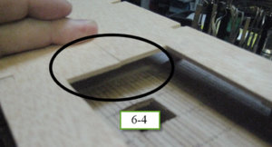
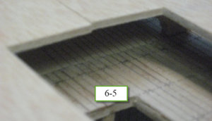
6-4 and 6-5 now the wall will not visible anymore
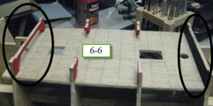
6- -6 Paint the wall red at the stern and black at the bow
1a.jpg1b.jpg1c.jpg1d.jpg1e.jpg1f.jpg
 
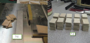
The instruction call for the installation at step18 of the bulwark of the forth gun deck that piece is the first of 4 that will place the gun port. Now those are long piece of plywood, and each opening need a piece of 15x15mm strong plywood of 3mm in thickness that will received the gun stump. OcCre supplied 4 length of 19mm x 60cm and I need 104 pieces. So out come my saw and I made a first cut to have 15x19mm pieces photo 7-1 7-2
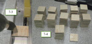
Follow by another cut to get the 15x15mm needed photo 7-3 7-4
Each gun port door are suppose to be in 2 part the outside cover and a lid that go inside.
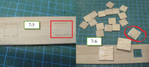
I have already build all the gun door cover and explain how I did it in my section post but for the inside part I decide to use the cut inside the plywood frame photo 7-5
After removing carefully those cut out I start to glue the 15x15mm gun support if you look at photo 7-6 you will notice 3 things.
First the gun support glue in place second the cut out remove and third on the right side just over the plywood frame you will see one gun port door with one cut out that will be install on it,
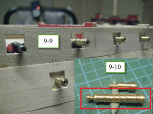
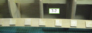
Photo 7-7 show the first side ready to be install
1a.JPG1b.jpg1c.jpg1d.jpg1e.jpg
 
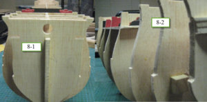
As you can see with the photo 8-1 the frame is very strait and 8-2 show the place where the gun frame for the forth deck is suppose to rest
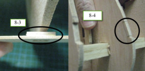
Now photo 8-3 show a problem that I saw when I did a dry test of those gun frame on 6 out of 10 the plywood of the gun support arrived right or really on the edge of the bulwark frame
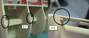
Photo 8-4 show the space that I did that will received the part photo 8-5 all of them done
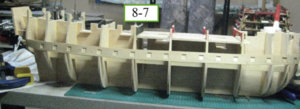
Photo 8-6 show how the part fit nicely and 8-7 the frame glue in place
1a.jpg1b.jpg1c.jpg1d.jpg
 
I have installed the second and third gun port plywood template that will be photo 9-1 and 9-2
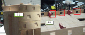
Photo 9-3 show the difficulty at the bow the plywood has to be bent and twist to fit properly.
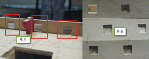
The photo 9-4 and 9-5 show the portion of the deck 3 that will need some scratch build from my part and that give me actually a nice challenge.
I decide at this stage to position and drill the hole that will received the stump gun later.
The reason I did it now is because if something happen to the base when the hull is close I will be in trouble. But doing it now when everything is accessible I can repair it easily that will be photo
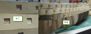
Photo 9-6 position the center 9-7 made a small hole with a punch then just drill the hole.
Just for the fun of it I install the entire stump for the first 3 decks that give a nice looking photo 9-8
Here the first fun for that kit and some challenge. As I have decide from the beginning to add the gun assembly of the portion of the third deck that will be visible That the reason that I did not follow the sequence of building because when the top deck is install it will have be impossible to install them. Then I start to realise that it was not simply add 12 gun carriage if you look at photo 9-9 you will see that the gun muzzle are not identical to the stump you have a close up with picture 9-10
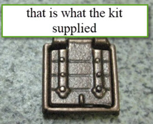
Now the kit supplied gun for the forth deck in sufficient number they are suppose to be 8pd but are not even close to what they are suppose to be. If you look again at the picture 9-10
You will see what I try to explain that type of gun barrel was use in the 16 century not in the 19 plus they are 27mm in length and completely inaccurate as the 8pd in the Spanish navy at that time where 1950mm in length so at 1:90 that give you 21mm look at the following chart those are for the ST at Trafalgar.
CañónCalibre mm.Longitud mm.Alcance (bala rasa 15º)
36 Libras17526473326
24 Libras15326473113
18 Libras13925083028
12 Libras12222293071
8 Libras10619503100
So having establish that the 8pd supplied with the kit are not adequate and that I will have to replace them with new one I decide to do as Andrea (Fam) did with is ST third deck
I will use the gun supplied cut the barrel drill a hole for the stump made new carriage from scratch rig them and install them at their position on the third deck making certain that the alignment is adequate Paul with is victory did give me a good lesson on that subject. The making of those gun will be the next post.
1a.jpg1b.jpg1c.jpg1d.jpg1e.jpg
 
12 Pounder third deck
The kit do not include gun for the 12 gun emplacement of the launch well. They supplied stump that are install on the plywood form.
From the beginning I want to install gun and rig them even if they will be barely visible call that pride if you want (my lady said that I am crazy) anyway I have in my head to place some gun there.
My first problem was that if I buy gun from what is available in store it was impossible to find gun with muzzle identical to the stump so I will have end up with 6 gun with muzzle different of the rest. The second problem is that from one end to the other I got 3mm in height difference (NO mistake from my part that the way thing go so I have to construct a carriage that will take that in consideration.
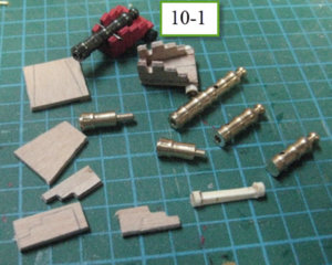
After a few e-mail exchange with Andrea (Fam) I decide to do the same as he did. Photo 10-1 show all the part prepare and one gun complete. I start with the gun, I use the one supplied in the kit cut a part made a hole in the frond and put the stump in it and in the end I got my 25mm gun barrel that is conform to a 12pounder at 1:90 scale. For the carriage usually (on the section ) I use popsicle stick but this time the thickness of the wood will have be too much as the 2 first gun emplacement are almost flush to the deck so I need something very low profile. A few day ago Paul show us is new carriage for is Victory and I ask him what kind of wood he use. It was left over plywood and I just got plenty of those. Made my design cut glue and I got the carriage that I need very low profile. As I need only the rear wheel axel I did not put any in front and where I will need to elevate the front I will just have to put a small wood shim in the front. After the basic rigging needed done it will be ok.
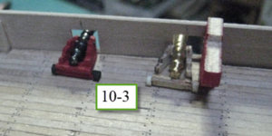
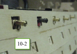
This photo 10-2 show how it will look all the muzzle identical and in line
This photo 10-3 show where I got another problem as the bulkhead arrive on the side of the second gun emplacement that something that I still have to think about.
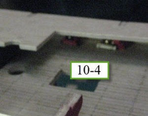
The last photo 10-4 show you how the gun will be barely visible when the forth deck is install. But the rigging in the back will be visible and need to be done
It might not look a lot for now but I am certain that when all install and rig they will look good1-a.jpg1b.jpg1c.jpg1d.jpg
 
Now with the Burrow (Arrow) complete I am back to the Santisima
As this ship is a commission for my older son, he was teasing me to when he will be able to have it so back to it
First thing to do is to clean my work area Picture
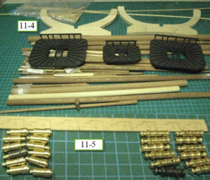
Ok after a year make a verification of all the parts and component and also make a verification to be certain the component that I have prepare in advance when I build the section where not damage already a few thing where done the 3 fighting platform and all the mast and spar are already done and ready 11-4
Ok back to work in the last post I was about to do the first modification to the kit that was the installation of 12 pounder on the third bridge.
Already some ground work was done, that is the how and the why. If you recollect my main problem was the impossibility to find stub and full gun that was similar so my option was to make something that was when view from the inside look like rig gun but from the outside was exactly like the stub supplied.
So my solution was to make new barrel that will give me the latitude to rig them but that the gun muzzle will like the stub supplied, so I cut some extra gun that I have drill a hole in the center and put the stub in place and that give me new gun I took that idea from Fam he did something similar for his Sea Howitzer. Another benefice of having stub on those it is that when I will plank the hull no danger to hurt the gun and break them looses as nothing is extended out of the hull.
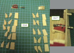
So picture 11-5 and 11-6 show all the part prepare and ready to be install I rebuild the carriage that was wrong and build a new model
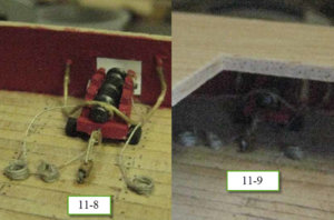
11-7 the first gun in test position and 11-8 place and rig
11-9 is the gun under the forth deck and you see the part that will be visible
Another thing that was important was the distance and the angle that the muzzle was to have on the visible part of the hull tanks to comment by Paul in his Vic I remember to take this in consideration picture 11-10 show the first gun in the extended position.
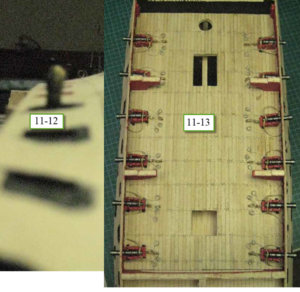
The Picture 11-11 the first series of 6 gun install and picture 11-12 show you the perfect alignment on the hull (sorry for the bad focus)
And 11-13 the 12 x 12 pounder of the third deck complete
1b.jpg11 (1).jpg11 (2).jpg11 (3).jpg11 (4).jpg11-5.jpg
 
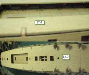
Picture 12-1 show what is visible after the forth deck is in is proper place of the gun on the third deck I am happy of the result
complete deck that will be cover by 1x3mm plank
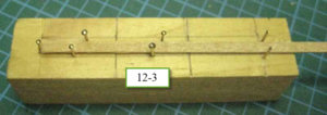
I have decide to use the same ratio that I have use on the section that was 60-40-20mm plank I build myself a small rig to cut my plank something easy to use and not complicated 12-3
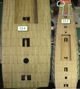
The deck is now complete 12-4
Lots to explain on 12-5
First in white I brook one of the supports that will to have to be repair
Second the red first is the small line just after the hole that will received the mast it is there that the wheel of the ship was suppose to be but on the model Ocre just build a wall that the purple line that you see. So to be able to install that wheel and be able to see it I will have to cut the back of the wall in red at the stern and build new wall in green so a view will be created true the castle
But I still have time but just in case I have complete deck planking all the way to the stern wall
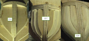
12-6 to 12-8 is how I help myself at the bow by putting extra wood to make it easier to do the hull planking there
1a.jpg1b.jpg1c.jpg1d.jpg12-2 is the
 
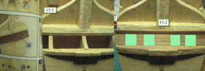
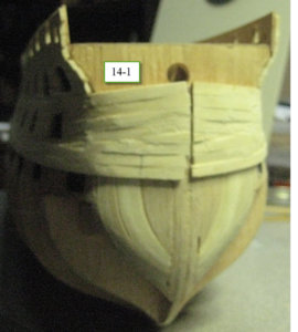
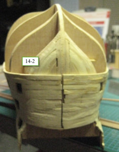
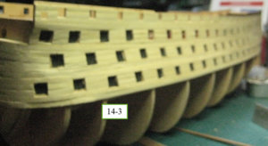
Hull planking start with a small portion at the stern 13-1 show how it is to be done and 13-2 how I di dit now in 13-2 you see 4 green square, the ship did have 4 chase gun emplacement at the stern something that the kit do not show so when the hull is complete I will probably add them there, I don’t know yet how I will do it but they will be add.
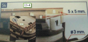
To avoid myself some problem and to make my life a bit easier I made some advance build. At the bow you have 2 davit that have to be install at some angle 13-3 the hole for it are made really late in the build step 54 13-4 so I decide to prepare them now when the hull is not planked
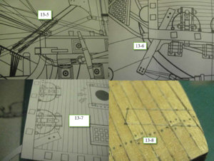
The instruction do not give any dimension to place them at all, the only indication is what you see in 13-5 and 13-6
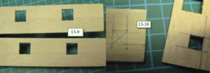
So what I did is make a photo copy of the scale drawing 13-7 and trace the position on the deck 13-8 that done I spot the position on the bulkhead 13-9 and 13-10 and when I did the planking was able to give the proper angle to the hole
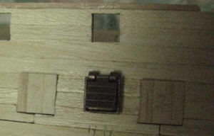
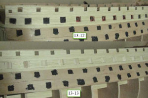
The kit came with cast gun port with a frame 13-11 what I did was the same as I did on the section build proper gun port 13-12 and 13-3 when the hull will be paint the hinge add and the drip protection in place it will be real nice I think
1a.jpg1b.jpg1c.jpg1d.jpg1e.jpg1f.jpg
 
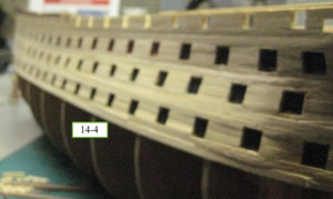
I have now complete the planking of the 4 gun deck.
All the gun emplacement are now done
A lots of sanding will be necessary but when that done it will be ready to received the rubbing stake. Next step is doing the hull it will be easy as I do not have to do a perfect work as the hull will be coppered lots of sanding to do
1a.JPG1b.JPG1c.JPG1d.JPG
 
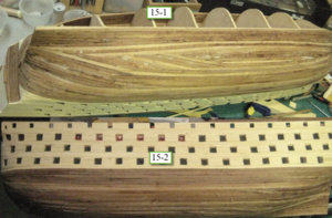
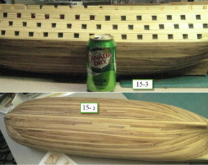
I have complete the planking of the hull
15-1 is the first side done
And as you can see with 15-2 and 15-3 it is a huge hull that ship when complete will take lots of space luckily for me it is not my problem it is my older son problem
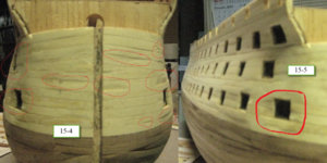
It was mention here in the forum at one point that picture do show defect that we do not usually see so I am now using that method to see defect and to correct them 15-4 and 15-5 are example of that so what I do is taking a lots of picture on all angle and spot where thing do have to be corrected
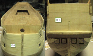
15-6 shows the bows where I think I did a good job as the plank do arrive equally on each side but of course it will be barely visible. That picture gives a good view of the deck where lots of work will have to be done
The black square on 15-7 show where I will put approximately the stern gun port chasing gun they are not parts of the kit so this will be a customise add to be historic the real ship. I have just to think how I will do it without making that wood section week by cutting the wood to do the door
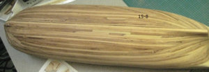
15-8 the complete hull sand now as I did not really care of the look of the hull it is not pretty it was not important as the hull will be copper plated
1a.JPG1b.JPG1c.JPG1d.JPG1e.JPG
 
It is a small one
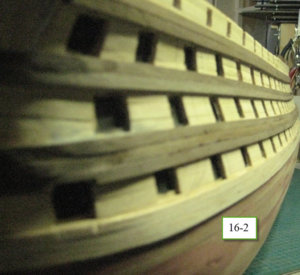
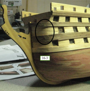
At this stage I install the rubbing strake the bow stern and the keel 16-1 16-2 and 16-3
As very visible on 16-3 I will have to make some sanding to correct some wood imperfection
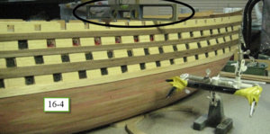
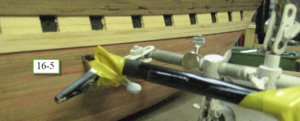
Now 16-4 and 16-5 is how I did my water line aI make the hull level that just pas the pencil along the hull
1a.JPG1b.JPG1c.JPG1d.JPG1e.JPG
 
Last edited:
That is one of the major modifications on this model
As this is a build on commission and my son want it as accurate as possible to the 1805 Trafalgar version the hull must be copper plated
Ok First I try with copper tape (Model Shipways MS0976) I read carefully the instruction given wit the Syren and did try it 17-1 show that the result was not nice at all so plan B
17-1a show top what I use on the section Model Shipway MS0978 6x12mm plate did not like the look rivet to big
So I change for the Mantua Plate 6mm x 17mm I start again and did like a lots more the result 17-2 show the new look I also did as they suggested I start at the stern.
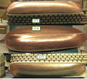
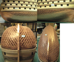
17-3 to 17-9 is the result of my work a total of 1645 plate where use It was mention in a site that 2400 plate was necessary that might be true if you use the plate supplied by Model Shipways as they are 12mm x 6mm that the one I have use on the section by the way and are not as good looking as the Mantua one the rivet are a lot bigger and do not look good so I suggest to use the Mantua one
Note: After a few year the plate did have a real nice platina
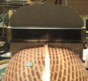
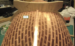
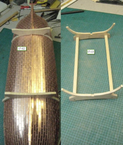
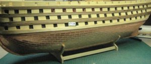
The next 5 picture 17-10 to 17-14 show how I made easily a cradle for the ship
Using a carpenter counter form 17-10 I first prepare a basic gauge of the hull
Then transfer it directly on a piece of wood
17-11 show the result for this I use Maple as it is a hard wood
I repeated the operation and 17-12 and 17-3 is the result
The ship got now a solid and stable cradle to be safe 17-4

1a.JPG1b.JPG1c.JPG1d.JPG1e.JPG1f.JPG1g.JPG
 
Last edited:
Back
Top