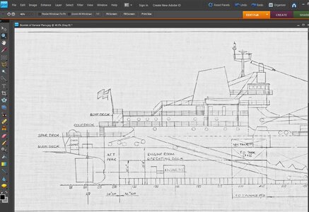
Shipyard prints in .pdf - general question

Joined
Feb 14, 2021
Messages
49
Points
68

Location
Windsor, ON
I have recently received some .pdf (and .jpg version) shipyard prints for a future build I want to undertake. The problem is, they are scanned from original (fragile condition it seems) blueprints, which have a very faded brown colour to them, and the lines drawn are quite faint. Getting them printed at a print shop will just be a shaded background with quite faint lines. I have tried printing them thru Acrobat reader and scale down to the size I need (using poster print feature and cutting/taping together) just to see how it comes out - well it's even fainter, more blended together almost.

Is there any way to darken the lines on a file like this?
 
Last edited:
TJ sent me the files on the drawings and the first problem encountered is the sheer size. The drawings are 1/4=1 foot scale making the drawings from stem to stern 15 feet long at 400DPI which is more than photoshop could handle. The drawing is in 2 parts from center to stern and from center to the bow and these are way to large to open in Photoshop. Because i get an error when trying to open the file in Photoshop i can not reduce them to a workable size. So i needed another way to work with the files.

This is a common problem when getting files from museums and collections they are huge in size. I found this out when i got the files on the steamer Mississippi,

so if it is ok with TJ i will post what i did with the files
 
By all means Dave. Hopefully this will be able to help others as well.

I was surprised, being new to the model building world, when I got the files from the Great Lakes Historical Collection, that not only were they actual scans from American Shipbuilding, but the size of them - physical and file size. I actually had to set up an account and send the link, as they were too big to actually send in an email. I wouldn't hesitate to get drawings from them again, as a lot of my fellow model laker builders use them, especially for older ships.

Also, at least around here, it is darn expensive to get pages that large printed.
 
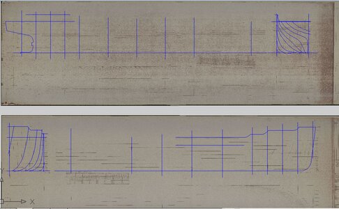
as i said these files are way to big to use in Photoshop so what i did was use AutoCad because CAD does not import the file it just links to it.

you can not see anything at full size because these 2 files are around 7 feet long
TRACING.JPG
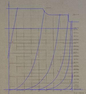
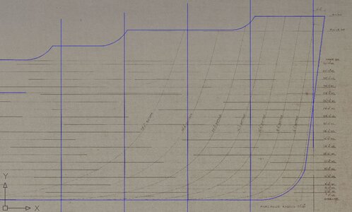
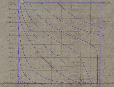
but when you zoom way in the image becomes visible so i could trace the bodylines
PIERSON OFFSET3.JPG

PIERSON OFFSET4.JPG

PIERSON OFFSET6.JPG

the problem is when you pan or zoom in or out or any movement of the drawings it takes a long time for the image to regenerate. So every move required processing time. A real pain in the... anyhow

once i had my tracing i can turn off the layer with the image and now work with just the drawing.
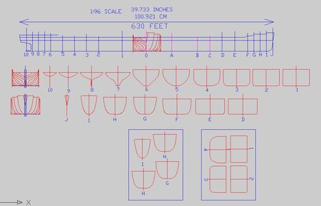
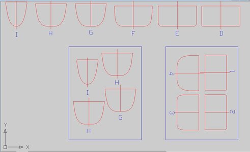
First step was to scale the drawings personally i always scale my drawing to the model i intend to build, i do this because i am either fitting parts on sheets of wood for laser cutting or setting the drawing up for printing, so i need to know the size of the parts.

TJ said he was building the model in 1/16 inch = 1 foot 1:96 scale
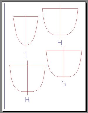
the square boxes at the bottom are 8 1/2 x 11 paper so the bulkheads can be printed on your average home printer. Some CAD users insist the paper size for a drawing should be set. I find no need for that because Auto Cad has lots of print options and i use the "print window 1:1" simply select the part you want to print and hit PRINT
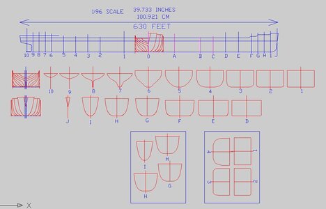
PIERSON BULKHEADS.JPG


i did not trace the hull lines because TJ is building the hull by sheeting over bulkheads. Now if this were to be a solid hull i would need to trace the hull lines to create lifts.

This was just the start of such a built. i recognize this is a steel hull bulk Great Lakes freighter. Living in Cleveland on the lake i grew up seeing many of these. Ev and i were even a guest passenger on board one and sailed from Cleveland to Duluth and back.
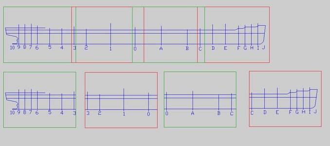
Anyhow, back to the drawing i do not have a profile or drawings showing the deck structure, just the hull shape. First i matched up the bodylines to the station lines and notice i have more stations than bodylines hum? seems 0 , A , B and C are not drawn on the plan.
But there is the offset chart.
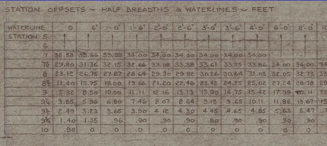
PIERSON OFFSET2.JPG
PIERSON OFFSET5.JPG

what i am thinking is this hull is one big square box from station C to O so i can go by the numbers and plot out the mid section. Also the plan shows the height of the poop deck but not how far forward, that info must be on a profile drawing. The two lines running the length of the ship is the top one is marked "spar deck" and the lower one "main deck"

the station lines on the profile do not have slots drawn for the bulkheads and the bulkheads have just a centerline because drawing the slots depend on the thickness of the plywood used for the model.

for anyone thinking about ordering a copy of plans from an archive or museum don't order scans of the original plans or you will get huge unmanageable files. what i do is order an 8 x 10 photograph of the plans, if that is an option, if not then you have to deal with big files.
 
TJ sent me the files on the drawings and the first problem encountered is the sheer size. The drawings are 1/4=1 foot scale making the drawings from stem to stern 15 feet long at 400DPI which is more than photoshop could handle. The drawing is in 2 parts from center to stern and from center to the bow and these are way to large to open in Photoshop. Because i get an error when trying to open the file in Photoshop i can not reduce them to a workable size. So i needed another way to work with the files.

This is a common problem when getting files from museums and collections they are huge in size. I found this out when i got the files on the steamer Mississippi,

so if it is ok with TJ i will post what i did with the files
1/48 scale (1/4"=1 foot)
 
that is correct Phil
the drawings are 1/4 inch to 1 foot scale 1:48 the hull is 630 feet long so at that scale the drawing is 13.125 feet long.

now to print the bulkheads for model building

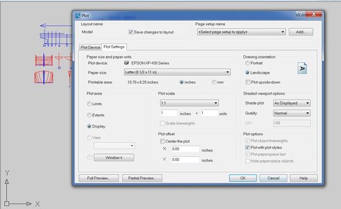
click plot and you get this window under the tab plot device i select the Epson printer then click plot settings and select the paper size seeing the max size of the printer is 8 1/2 x 11 i set the paper size at that. some printers will print 11 x 17 so you can set your paper for that size. Next is plot scale make sure it is 1:1 and set the plot orientation. Now you are set up.

click WINDOW in the lower left corner

PRINT1.JPG

you will get a drawing view

PIERSON BULKHEADS.JPG

zoom in to the setup on the drawing the blue line is set at 8 1/2 x 11 so select it and click ok

PRINT3.JPG

click full preview and you will see what you selected to print

PRINT2.JPG

now if you do not have AutoCad then you have to save the drawing as a .DXF and import or open it another program to print it. you may have to save each 8 1/2 x 11 as separate files.
someone else will have to show how to print a DXF file or convert the DXF files into PDF files
 
to print the center profile you will need to break it down into several pieces to print and then tape them together.
notice i overlapped the images so you have the same station line printing on each sheet. What i do is tape one sheet to a window so when i lay the second sheet down i can see through it and line it up with the sheet underneath.

PRINT4.JPG
 
Last edited:
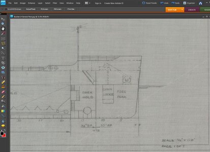
lets look at another sheet of drawings for the ship
this sheet is drawn in 1/16 scale which is a fourth the size of the hull line drawing so Photoshop can handle it.

PP0.JPG

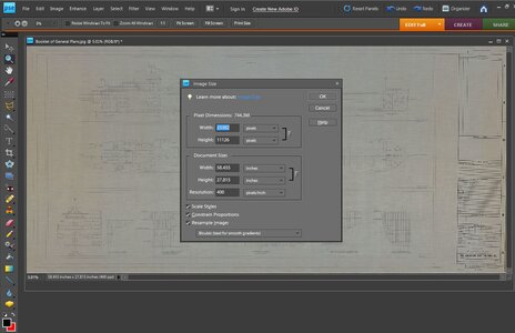
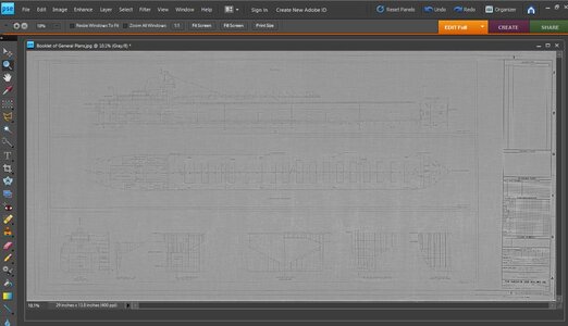
the drawing is 58.455 in width and is 744.3 megs in size really big so we have to get it smaller in order to work with it.

PP1.JPG


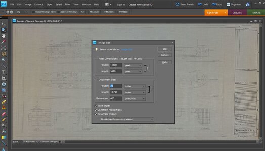
first lets reduce the width to half its size down to 29 inches now notice the megs went from 744 down to183

PP2.JPG

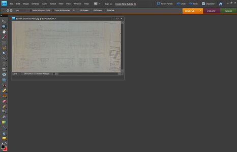
viewing it now it is half the size but still at 400DPI we don't want to change that.

PP3.JPG

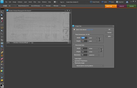
reducing the megs from 183 down to 61 and i did that by changing the mode from RGB to gray scale notice the blocks in the lower left corner. I got rid of the color because we don't need color for the drawing.

PP4.JPG

after we reduced the file size to a manageable size lets tweak it and pull out some detail.

PP5.JPG


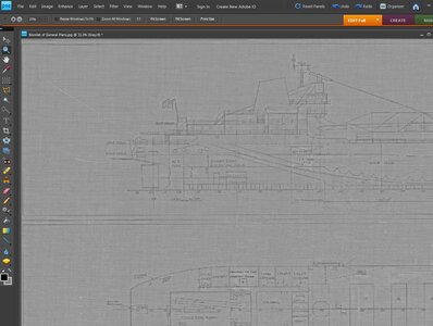
lets zoom in to a section of the drawing and see what we have.

PP6.JPG

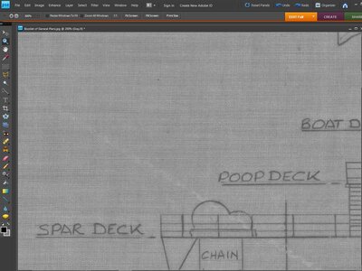
because i still have a high resolution of 400 DPI you can actually see the weave of the linen the drawing was done on.

PP7.JPG

step one is playing with contrast and brightness

PP8.JPG

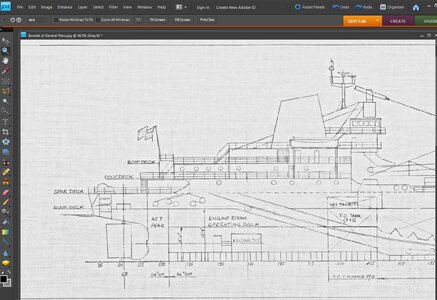
step two is tweaking the drawing to remove as much of the back round and sharpen up the lines.
We now have a clean clear drawing from 744 megs down to 61 megs and the resolution can be reduced from 400 to 200 and still have a sharp image of the drawing at around 30 megs.

PP9.JPG
 
Never realized this would have originally been drawn on a linen material. I was figuring a thin paper or mylar.

Also, for us Great Lakes freighter modellers - the 1/16" - 1ft scale is the most common build size. I am learning that is likely because most drawings are done in that scale, or easily scaled from 1/4" - 1ft or 1/8" - 1ft to that size, and it is a good working size for a model of a ship that big. Plus it seems like fittings are quite readily available in that scale too. You get a 730ft (or in this case a smaller 630ft) in a display friendly size of 4ft or less.
 
Another tool you can use to help reduce file size is to use "Save for the Web" tool when saving your file. Photoshop helps optimize the file and filesize.
 
I have recently received some .pdf (and .jpg version) shipyard prints for a future build I want to undertake. The problem is, they are scanned from original (fragile condition it seems) blueprints, which have a very faded brown colour to them, and the lines drawn are quite faint. Getting them printed at a print shop will just be a shaded background with quite faint lines. I have tried printing them thru Acrobat reader and scale down to the size I need (using poster print feature and cutting/taping together) just to see how it comes out - well it's even fainter, more blended together almost.

Is there any way to darken the lines on a file like this?
 
Don't dismiss having a store copy them for you so Quickly. They can adjust the copy settings to improve them, hopefully enough to make them more legible. You can also use them as a reference drawing in Autocad, or similar, and trace them. The autocad drawing will be much more useful (scale up or down, etc) than the original. Plus you will always have a good copy. It's a lot of work but I think it's worth it.
 
that is correct Phil
the drawings are 1/4 inch to 1 foot scale 1:48 the hull is 630 feet long so at that scale the drawing is 13.125 feet long.

now to print the bulkheads for model building

click plot and you get this window under the tab plot device i select the Epson printer then click plot settings and select the paper size seeing the max size of the printer is 8 1/2 x 11 i set the paper size at that. some printers will print 11 x 17 so you can set your paper for that size. Next is plot scale make sure it is 1:1 and set the plot orientation. Now you are set up.

click WINDOW in the lower left corner

View attachment 224639

you will get a drawing view

View attachment 224642

zoom in to the setup on the drawing the blue line is set at 8 1/2 x 11 so select it and click ok

View attachment 224641

click full preview and you will see what you selected to print

View attachment 224643

now if you do not have AutoCad then you have to save the drawing as a .DXF and import or open it another program to print it. you may have to save each 8 1/2 x 11 as separate files.
someone else will have to show how to print a DXF file or convert the DXF files into PDF files
Just to understand do you measure the length of the model drawing in Auto Cad and then scale it to the proper length? 39.733 inches
 
I drew in AutoCAD at full scale. 1:1. If I needed to scale a drawing, it happened in the plot setup.
I agree when I draw in auto cad but I am importing a JPG file and need to make it the proper scale.
 
Back
Top