• LUCZORAMA SHIPWRECK SCAVENGER HUNT GIVEAWAY. 4 Weeks of Fun • 1 Legendary Prize ((OcCre’s Fram Ship)) • Global Crew Welcome!
    **VIEW THREAD HERE**

Shroud rigging

Joined
Aug 22, 2022
Messages
249
Points
78

This photo of the shroud sequence:
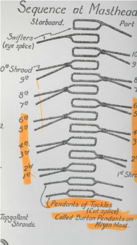
1742329642067.png

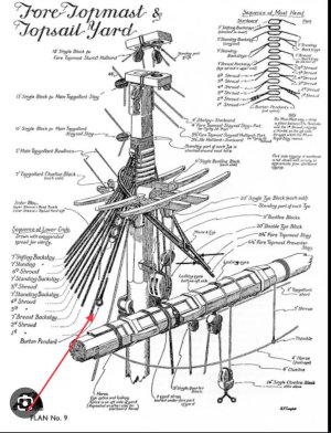
...is from Longridge, Plan #9, between pages 228 and 229. Has anyone had experience constructing the shroud shown at the bottom, the Burton pendants, which go on the mast first? This seems it should be a "throat" seizing (Longridge, page 217, fig. 149) to put the port and starboard shroud together. Tension would have to be taken up at the and between the two dead eyes but would not be on the mast as with the other shrouds.Any suggestions for a good way to make this. One could make a loop in one end of two 0.4mm strings, then cutting the loops open and "reassemble" them using two simulated long splices. I am going to try that unless I come up with something better. At this scale, it might not really matter but I'ld like to make it as realistic as possible.

Any suggestions would be appreciated and most helpful.

 
using two simulated long splices.
At this scale I think you are right. But, they were not rigged with deadeyes as they were only used for hoisting.
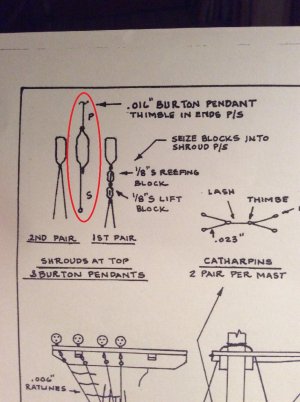
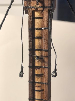
From James Lees' Masting and Rigging English Ships of War ---- After 1780 the pendants of the tackles were rigged with an eye splice if there was one port and one starboard. First and second rate ships had two per side and the cut splice would be used (as shown in the posts above.) In all cases they were served their entire length which was long enough to reach down to the upper catharpins. After 1780 a thimble was seized in the end of the pendant as Jay shows above. If two per side the after ones on each side were a foot longer than the forward pendant and again, after 1780 had a thimble in the end. Since the runners of the tackles were for hoisting. most contemporary models don't include them. If the runner is rigged it had a single and double block and is usually just tied off to a deadeye of one the shrouds. The rigging at the end of the burton pendants on the mizen mast and topmasts varied with time on British ships as well. Is this for your Victory cross section? If so, there would be two pendants on each side of the lower mast and one on each side of the topmast.
Allan
 
Last edited:
At this scale I think you are right. But, they were not rigged with deadeyes as they were only used for hoisting.
From James Lees' Masting and Rigging English Ships of War ---- After 1780 the pendants of the tackles were rigged with an eye splice if there was one port and one starboard. First and second rate ships had two per side and the cut splice would be used (as shown in the posts above.) In all cases they were served their entire length which was long enough to reach down to the upper catharpins. After 1780 a thimble was seized in the end of the pendant as Jay shows above. If two per side the after ones on each side were a foot longer than the forward pendant and again, after 1780 had a thimble in the end. Since the runners of the tackles were for hoisting. most contemporary models don't include them. If the runner is rigged it had a single and double block and is usually just tied off to a deadeye of one the shrouds. The rigging at the end of the burton pendants on the mizen mast and topmasts varied with time on British ships as well. Is this for your Victory cross section? If so, there would be two pendants on each side of the lower mast and one on each side of the topmast.
Allan
Thanks. I knew that about the beckets. With this cross -section there will be nothing to "use" the pendants for, I'm going for the look more than anything. You are correct in the number of pendants for the main mast. The fore mast had four at the top. I appreciate the feed-back!
 
I mis-wrote when I wrote that the beckets would be connected to dead-eyes. I appears that tension on these when in use would not not affect the vertical stability of the masts, just the vertical as they would exert a downward force/pressure on the mast via the top. Interesting how one can learn something about the physics of shipbuilding by constructing a model as many of the same forces on the real ship can be observed in the miniture versions.
 
I had this same question on my current build of the Prince De Neufchatel. The one circled in red was how I made mine by splicing two lines into the one.

I noticed you listed the Jolly Roger by Lindberg. OMG! We built so many of these as children, poured melted wax into the hull, and had naval battles in the tub and the park pool. Great fun.
 
Intriguing question, and I went to my 'Steel's Art of Rigging' only to find that, whilst listed variously as named Pendents, the mizen-burton pendents and topmast burton-pendents simply say
'prepared on -shore, have a cont-splice in the middle to the circumference of the mast-head ; thimbles spliced in the lower ends, and served with spunyarn over the splices.
George Biddlecombe in 1848 seems to have lifted his description in 'The Art of Rigging' wholesale from David Steel's 1794 volume, so I suppose he felt that nothing had changed. There isn't, after all, any change needed to a simple, working solution.

- Incidentally, I've never quite forgiven Steel for giving me incorrect information about the standing rigging for my 'Thermopylae' back in 1974. In his defence though, I didn't know better. But I was never happy with that model, despite my errors being invisible. I knew it was there....
Moral - do proper research, and ensure the dates are correct.


J
 
Don't feel bad about Steel. There are a couple errors in the scantlings in The Elements and Practice of Naval Architecture as well, having switched the inches and feet. for a couple items. For the life of me I cannot remember which scantlings these were. The errors are supposedly original, and carried over in the re-print by Sim Comfort in 1977. Some, if not all the errors were corrected in the Scantlings p of Royal Navy Ships, published in 2014. Stuff happens, and as you say, doing proper research of multiple sources is a very good idea.
Allan
 
Last edited:
Maybe I should clarify my comment a little. Steel was writing well before the clipper era, so the fault, as I know only too well, was not really 'his' - it was mine. Being a callow youth back then, with his first 'proper' model, I was eager to finish, and had that youthful trust in book learning, so I never considered the possibility of needing to find contemporaneous description that fitted the ship.
When you've grown up a couple of decades you know that you can't trust a single source, and you can't trust the government to act in the best interests of the public, and so on.

It was an original copy of Steel, in Leeds reference library, brought out for me from some underground store a long, long walk away. Magnificent old book. I hope they still have it.

J
 
@icebiker3 I noticed you listed the Jolly Roger by Lindberg. OMG! We built so many of these as children, poured melted wax into the hull, and had naval battles in the tub and the park pool. Great fun.

I still have an one in my stash to build I bought on clearance when I built my first one. I built it as my own Privateer, and will do the second as the La Flore.
 
The Industrial Revolution had an effect on sailing ships often ignored by authors of popular history. As a result they lavish praise on the beauty and speed records of the Clippers Ships but fail to mention the innovations in rigging that helped to make these speed records possible.

By the mid 1800’s ironwork had made its appearance in the rigging of these large vessels. Examples: iron trusses, chain tyes, etc.

Steel’s work reflected late Eighteenth Century state-of-the-art; a different world from that of the Clippers.

Roger
 
Back
Top