

Part 1 Sloop of War Austin Design
In a previous post to this forum I wrote about my model of the Texas Navy schooner Invincible. This post , about a second Texas Navy vessel I am currently working on, the sloop of war Austin, will cover a number of subjects. The first concerns the search for sources of information that would allow building a representative model and the development of a vessel plan. Next is converting the plan to templates for bulkheads and a keel piece for building a model by the plank on bulkhead (POB) method. This is followed by assembly of the framework and finally the remaining steps in constructing the model.
After the loss of the first four schooners obtained for the Texas Navy , including Invincible, during the war for independence from Mexico, a new navy was created in 1838 with the construction of 6 sailing ships by Fredrick Dawson in Baltimore and the purchase of a paddle wheel steamer ( http://www.texasmilitaryforcesmuseum.org/articles/texasnavy/texasnavy.htm). One of these ships, Austin, made history at the Battle of Campeche in 1843 by being the only sail powered vessel to fight an iron hulled steam warship to a draw.
As was the case with modeling Invincible, plans are not available for Austin. But at least for Invincible, a plan for a similar vessel by the same builder served as the basis for the model. Much less is known about Austin. The only source I have been able to locate for the designer is Howard Chapelle in his book “The American Sailing Navy” (W.W. Norton, 1949). On page 407, the design is attributed to U.S. Naval Constructor Francis Grice, but later on in the book he also says that Grice's papers remain missing so it is a mystery as to where Chapelle got his information. Her dimensions were 125' between perpendiculars, 31' breadth, and 12'6” depth of hold, corresponding to a tonnage of 600. Armament is stated to be 16 24pounders and 4 18 pounders which would require a minimum of 10 gun ports per side. Chapelle gives a significantly different depth, 15'10 1/2”, but the 12'6”depth is confirmed by a report of a survey of the Austin in 1846 stating she draws 3' less than any U.S. sloop of war which was typically about 15'.
The only known image of Austin was painted by Edward Johns who was a midshipman aboard her (Naval History and Heritage Command, www.history.navy.mil):

It is obviously unfinished. Rigging and channels are only shown on the bowsprit and foremast. There is a square stern, no quarter galleries, and the head is planked in. The low placement of the guns in the hull suggests the presence of a spar deck. However, the preponderance of evidence for sloops of war from this period indicates that she would be flush decked, so the low placement is perhaps artistic license.
Given the lack of design information for Austin, any model of her would be pure conjecture, so why bother? We are all familiar with conceptual ship models. Most models of ships prior to 1700 are from plans based on maritime historians best guesses. These models, the when on public display, serve a purpose. Yes, they do not replicate the actual ship, but when based what is known about typical vessels of their era, they can certainly provide a glimpse of what sailing ships of the time looked like and emphasize the history of the events they took part in.
The sloop of war was a very popular design for U.S. Naval ships in the period following the War of 1812. Smaller than a frigate, but well armed and capable of long cruises, they filled the need to protect America's growing world wide trade. This class of vessel is extensively discussed in “Sailing Warships of the US Navy” by Donald L. Caney (Naval Institute Press, 2001) and “The American Sailing Navy”. In this latter book, Chapelle presents many sloop of war plans. In the absence of a specific plan for Austin, the only alternative for building a model is to select a plan for another vessel that is a fairly good match. The best choice was Germantown (1843) whose dimensions were 150' length between perpendiculars, 36' breadth, and 16.8' depth. This is much larger than Austin, however the length to breadth ratio is similar (4.16 vs 4.03), so reducing the size of the plan by 17% would give the desired length and breadth. However, the depth will be 14' rather than 12.5'. The reason for Austin's shallow draft may be related to her design for the Gulf of Mexico.
The plans for the Germantown from Chapelle are shown below:


Germantown has an elliptical stern and quarter galleries as compared to Austin's square stern and lack of galleries. To match Austin's appearance in the illustration above, the stern area was redrawn and the quarter galleries omitted on a revised plan. Also the gun deck was shifted down by 1/16” on the scaled plans to maintain a height of 6' (full scale) under the poop and forecastle decks. No other corrections were made in depth on the plans to better match Austin's depth.
A spectacular model of the Austin built by Wayne E. Crow, was donated by his family to the Texas Military Forces Museum in Austin, Texas. Mr. Crow has passed away so I was unable to get any information from him about his design basis. The model, as shown below, is 57” long and has a full set of ship's boats, copper plating, and furled sails among the many other details.

The deck layout is very similar to the Germantown so he may have travelled the same road as I did in searching for a representative plan. I believe this model is likely at a scale of about 1/48. After a consideration of space limitations, a scale of 1/85 was chosen for my model. This results in a hull 20” inches long (stem to stern) and 4.25”inches wide.
Part 2 Developing Templates
In this section I will discuss converting the plans to templates for cutting out the bulkheads and keel piece for this plank on bulkhead model. But first, for any readers contemplating scratch building, I want to mention the need for some power tools. A scroll saw is useful for cutting out the bulkheads and other curved shapes on the model, and a miniature table saw is essential for converting sheet wood to planking strips. I have a PREAC saw which is no longer manufactured, but other brands are currently on the market. I also use a sanding drum in my drill press for final sanding of shapes. My bench set up is shown below:

The cost of these two saws would be in the vicinity of $500, but it can cost that much for a single kit, and the expense for a scratch built model in my experience is less than $100, mainly for wood. I also find a Dremel drill (or similar brand) to be essential and a Dremel drill press to be very useful.
My first step in the build was to use a copying machine to print Chapelle's plans in the desired scale. Since the model is longer than the 14” paper available in most copiers, the copies were made in sections then taped together. A template for the keel piece was obtained from the shear plan. The upper surface is determined by the position of the decks. Starting aft there is the poop deck, a drop off to the gun deck, then a rise to the forecastle deck. The deck is open under the forecastle. So that none of the keel piece will show on the model, the aft-most bulkhead under the forecastle was inset about 1.5” from the aft edge of the forecastle deck. Some plans show the top and some the underside of the deck. If the top is shown, shift the deck lines downward to account for deck thickness. Slots for the masts were drawn on the plan and slots for the bulkheads were drawn at each station line equal to half the depth of the keel piece.
The body plan, one side of which shows the vessel cross section at the forward station lines and the other half at the aft station lines, was copied to the desired scale and then copied again using the mirror image function available on most copying machines to flip the image. The original and flipped images were then carefully cut along the center line and the matching halves taped together to give full cross sections. The result is shown below.

Duplicates of these plans were then made corresponding to the number of bulkheads on the model. Excess paper was cut away to give the outside lines for each bulkhead. To convert the plans to bulkhead templates the position of the deck has to be determined. I do this with a T-square and drawing board.
The shear plan is taped to the board with the keel horizontal. Then, one by one, each bulkhead is laid on top of the shear plan near its station line, and the water lines on the two plans are lined up to insure correct placement. Then at every station line the T-square is used to carry the height of the deck at the centreline onto the body plan at that position. This set up is shown below:

I also check to insure that the shear on the hull plan corresponds to the position of the shear on the bulkhead plan. One of the cross section plans for Germantown shows the camber of the deck. This was traced onto a piece of card and cut out to produce a camber guide. The guide is laid on the bulkhead plan and the entire deck line is drawn through the centerline mark. Finally, a slot was marked on the bottom on the bulkhead with depth equal to the corresponding slot on the keel piece and extensions were drawn from the deck line to the sheer to support the bulwark planking above the deck. As usual with POB construction, these will be cut off after planking is complete. Sample bulkhead templates are shown below:

The keel piece and bulkhead templates were then glued to plywood. I use multi-layer aircraft plywood for the keel piece for strength. I don't believe the plywood used for the bulkheads is as critical, and I often use lumber supply 1/4” or 3/16” panelling scraps.
Part 3 – Building the skeleton
To start actual construction, the keel piece and bulkheads were cut out just wide of their reference lines and then sanded to the line. The exception being the bottom of the keel which was cut to the line with the PREAC saw to get a perfectly straight cut. The bulkheads were then dry fit into the keel piece to make sure they fit squarely into their slots, as checked with a square, and the waterlines on the bulkhead templates lined up with the waterlines on the keel piece. I'll just list the steps I next took before gluing the bulkheads into the keel piece. For the keel piece:
After the bulkheads were glued into the keel piece, sandpaper was wrapped around a long narrow piece of wood and a bevel was sanded along the edges of several bulkheads at a time so planking would lie flat when glued on. Test pieces of planking were next laid along the hull and any areas that were not fair were either built up or sanded down. Pieces of 1/4”x1/4” basswood were glued between the bulkheads to stiffen the hull, although that was probably not necessary for a hull of this length.
In most POB kits, the edges of the sub deck are not supported, and I have found this leads to problems later on when planking the deck. So I next cut notches for a 1/16”x1/16” deck stringer in each side of the bulkheads just under my marks on the templates for the edge of the deck. It was then glued into the notches and sanded flush with the bulkheads.
Finally, filler blocks were made to fill the space between the first and last bulkheads and the rabbets lines to support the ends of the planking at the stem and stern. The first plank layer would be 1/16” and the second 1/32” so the blocks were set 3/32” back from the rabbet lines.
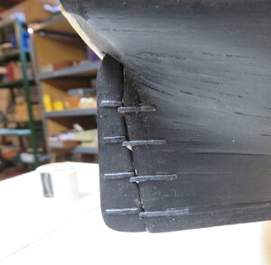
Next up was to cut rabbets where needed. At the stern I cut a rabbet and also removed some material in the deadwood area under the last couple of bulkheads which do not reach the keel. This is so the plank ends in this area will be level with the keel. If the first planking is terminated short of the keel and sanded down at the ends, the depth of the rabbet only has to be 1/32” for the ends of the second planking. This is shown in the below photo.

I cut a stem rabbet, but later in the build as I am adding planks. I do not cut a rabbet along the keel for the garboard since a fit can usually be achieved without a seam showing.
To complete the skeleton of the model, a card pattern was cut out to the shape of the deck, slots were cut to fit around the bulkheads, and the profile trimmed to be flush with the hull. It was then traced onto the sub-deck material, 1/32” aircraft plywood. The sub-deck was cut out and glued to the upper surface of the bulkheads as well as the deck stringer.
Part 4 Planking the Hull
In my previous post about the Invincible, I described my planking method so it will not be repeated here. In summary, the hull is divided with battens into planking sections each containing 4-5 planks. In each section the width along the bulkheads is measured, and then planks are tapered according to these measurements to fit between battens. Planks on this model were 5/32” wide corresponding to about 13” at full scale. I take as much care with the first planking as with the second. This serves as practice to indicate where stealers will be needed and where the battens might have to be shifted the second time around. I always install the first plank in a position where it will serve as a reference for later measurements. Usually it is either at a wale or just under the gun ports. For the Austin, the first plank was set along the the line of gun ports.
Planks are pre-bent by dipping them in water then shaping them over a piece of 3/4” copper tubing that is placed over the heated barrel of a soldering iron (bending over the barrel directly burns the wood). As each plank is installed, a notch for the plank end is cut along the rabbet line at the stem. I find this works well for me to get a good fit of the planks. The hull was first planked from the gun ports down to the garboard then up to the shear, which usually goes quickly since little plank taper is needed in this area.
The model after completion of the first planking is shown below.

The planks were sanded fair, and next was to installed the transom at the stern. The transom pattern was glued to 1/32” plywood, two ply pieces were overlaid, and two identical transoms were cut out. One (sub-transom) was glued in place and the other was saved to work on later. Windows and trim will be added to this piece on the bench, and later it will be glued to the sub-transom.
After gun ports were cut in, the second layer of cherry planking was applied. The bulkhead extensions above deck could then be cut off and the inside the bulwarks planked with cherry. The model at this stage is shown below. A trim molding has been added above the gun ports. The stem and stern fillers can be seen in this picture as well as where the gun deck rests on the deck supports glued to the faces of the appropriate bulkheads as mentioned earlier.

TO BE CONTINUED
In a previous post to this forum I wrote about my model of the Texas Navy schooner Invincible. This post , about a second Texas Navy vessel I am currently working on, the sloop of war Austin, will cover a number of subjects. The first concerns the search for sources of information that would allow building a representative model and the development of a vessel plan. Next is converting the plan to templates for bulkheads and a keel piece for building a model by the plank on bulkhead (POB) method. This is followed by assembly of the framework and finally the remaining steps in constructing the model.
After the loss of the first four schooners obtained for the Texas Navy , including Invincible, during the war for independence from Mexico, a new navy was created in 1838 with the construction of 6 sailing ships by Fredrick Dawson in Baltimore and the purchase of a paddle wheel steamer ( http://www.texasmilitaryforcesmuseum.org/articles/texasnavy/texasnavy.htm). One of these ships, Austin, made history at the Battle of Campeche in 1843 by being the only sail powered vessel to fight an iron hulled steam warship to a draw.
As was the case with modeling Invincible, plans are not available for Austin. But at least for Invincible, a plan for a similar vessel by the same builder served as the basis for the model. Much less is known about Austin. The only source I have been able to locate for the designer is Howard Chapelle in his book “The American Sailing Navy” (W.W. Norton, 1949). On page 407, the design is attributed to U.S. Naval Constructor Francis Grice, but later on in the book he also says that Grice's papers remain missing so it is a mystery as to where Chapelle got his information. Her dimensions were 125' between perpendiculars, 31' breadth, and 12'6” depth of hold, corresponding to a tonnage of 600. Armament is stated to be 16 24pounders and 4 18 pounders which would require a minimum of 10 gun ports per side. Chapelle gives a significantly different depth, 15'10 1/2”, but the 12'6”depth is confirmed by a report of a survey of the Austin in 1846 stating she draws 3' less than any U.S. sloop of war which was typically about 15'.
The only known image of Austin was painted by Edward Johns who was a midshipman aboard her (Naval History and Heritage Command, www.history.navy.mil):
It is obviously unfinished. Rigging and channels are only shown on the bowsprit and foremast. There is a square stern, no quarter galleries, and the head is planked in. The low placement of the guns in the hull suggests the presence of a spar deck. However, the preponderance of evidence for sloops of war from this period indicates that she would be flush decked, so the low placement is perhaps artistic license.
Given the lack of design information for Austin, any model of her would be pure conjecture, so why bother? We are all familiar with conceptual ship models. Most models of ships prior to 1700 are from plans based on maritime historians best guesses. These models, the when on public display, serve a purpose. Yes, they do not replicate the actual ship, but when based what is known about typical vessels of their era, they can certainly provide a glimpse of what sailing ships of the time looked like and emphasize the history of the events they took part in.
The sloop of war was a very popular design for U.S. Naval ships in the period following the War of 1812. Smaller than a frigate, but well armed and capable of long cruises, they filled the need to protect America's growing world wide trade. This class of vessel is extensively discussed in “Sailing Warships of the US Navy” by Donald L. Caney (Naval Institute Press, 2001) and “The American Sailing Navy”. In this latter book, Chapelle presents many sloop of war plans. In the absence of a specific plan for Austin, the only alternative for building a model is to select a plan for another vessel that is a fairly good match. The best choice was Germantown (1843) whose dimensions were 150' length between perpendiculars, 36' breadth, and 16.8' depth. This is much larger than Austin, however the length to breadth ratio is similar (4.16 vs 4.03), so reducing the size of the plan by 17% would give the desired length and breadth. However, the depth will be 14' rather than 12.5'. The reason for Austin's shallow draft may be related to her design for the Gulf of Mexico.
The plans for the Germantown from Chapelle are shown below:
Germantown has an elliptical stern and quarter galleries as compared to Austin's square stern and lack of galleries. To match Austin's appearance in the illustration above, the stern area was redrawn and the quarter galleries omitted on a revised plan. Also the gun deck was shifted down by 1/16” on the scaled plans to maintain a height of 6' (full scale) under the poop and forecastle decks. No other corrections were made in depth on the plans to better match Austin's depth.
A spectacular model of the Austin built by Wayne E. Crow, was donated by his family to the Texas Military Forces Museum in Austin, Texas. Mr. Crow has passed away so I was unable to get any information from him about his design basis. The model, as shown below, is 57” long and has a full set of ship's boats, copper plating, and furled sails among the many other details.
The deck layout is very similar to the Germantown so he may have travelled the same road as I did in searching for a representative plan. I believe this model is likely at a scale of about 1/48. After a consideration of space limitations, a scale of 1/85 was chosen for my model. This results in a hull 20” inches long (stem to stern) and 4.25”inches wide.
Part 2 Developing Templates
In this section I will discuss converting the plans to templates for cutting out the bulkheads and keel piece for this plank on bulkhead model. But first, for any readers contemplating scratch building, I want to mention the need for some power tools. A scroll saw is useful for cutting out the bulkheads and other curved shapes on the model, and a miniature table saw is essential for converting sheet wood to planking strips. I have a PREAC saw which is no longer manufactured, but other brands are currently on the market. I also use a sanding drum in my drill press for final sanding of shapes. My bench set up is shown below:
The cost of these two saws would be in the vicinity of $500, but it can cost that much for a single kit, and the expense for a scratch built model in my experience is less than $100, mainly for wood. I also find a Dremel drill (or similar brand) to be essential and a Dremel drill press to be very useful.
My first step in the build was to use a copying machine to print Chapelle's plans in the desired scale. Since the model is longer than the 14” paper available in most copiers, the copies were made in sections then taped together. A template for the keel piece was obtained from the shear plan. The upper surface is determined by the position of the decks. Starting aft there is the poop deck, a drop off to the gun deck, then a rise to the forecastle deck. The deck is open under the forecastle. So that none of the keel piece will show on the model, the aft-most bulkhead under the forecastle was inset about 1.5” from the aft edge of the forecastle deck. Some plans show the top and some the underside of the deck. If the top is shown, shift the deck lines downward to account for deck thickness. Slots for the masts were drawn on the plan and slots for the bulkheads were drawn at each station line equal to half the depth of the keel piece.
The body plan, one side of which shows the vessel cross section at the forward station lines and the other half at the aft station lines, was copied to the desired scale and then copied again using the mirror image function available on most copying machines to flip the image. The original and flipped images were then carefully cut along the center line and the matching halves taped together to give full cross sections. The result is shown below.
Duplicates of these plans were then made corresponding to the number of bulkheads on the model. Excess paper was cut away to give the outside lines for each bulkhead. To convert the plans to bulkhead templates the position of the deck has to be determined. I do this with a T-square and drawing board.
The shear plan is taped to the board with the keel horizontal. Then, one by one, each bulkhead is laid on top of the shear plan near its station line, and the water lines on the two plans are lined up to insure correct placement. Then at every station line the T-square is used to carry the height of the deck at the centreline onto the body plan at that position. This set up is shown below:
I also check to insure that the shear on the hull plan corresponds to the position of the shear on the bulkhead plan. One of the cross section plans for Germantown shows the camber of the deck. This was traced onto a piece of card and cut out to produce a camber guide. The guide is laid on the bulkhead plan and the entire deck line is drawn through the centerline mark. Finally, a slot was marked on the bottom on the bulkhead with depth equal to the corresponding slot on the keel piece and extensions were drawn from the deck line to the sheer to support the bulwark planking above the deck. As usual with POB construction, these will be cut off after planking is complete. Sample bulkhead templates are shown below:
The keel piece and bulkhead templates were then glued to plywood. I use multi-layer aircraft plywood for the keel piece for strength. I don't believe the plywood used for the bulkheads is as critical, and I often use lumber supply 1/4” or 3/16” panelling scraps.
Part 3 – Building the skeleton
To start actual construction, the keel piece and bulkheads were cut out just wide of their reference lines and then sanded to the line. The exception being the bottom of the keel which was cut to the line with the PREAC saw to get a perfectly straight cut. The bulkheads were then dry fit into the keel piece to make sure they fit squarely into their slots, as checked with a square, and the waterlines on the bulkhead templates lined up with the waterlines on the keel piece. I'll just list the steps I next took before gluing the bulkheads into the keel piece. For the keel piece:
- Where there was a companion way with a ladder, a section was cut out of the keel piece equal to the length of the opening and to the depth of the lower deck. A floor section of basswood was then glued to the bottom of this opening for the ladder to rest on when installed. The edges of the opening were painted black.
- Holes were drilled in the stem for the bobstays. Austin does not have a gammon slot, but one would be made at this time if needed.
- Holes were drilled in the bottom for later attaching pedestals to mount the completed model.
- Dowels were inserted in the mast slots to insure good fit and the right mast rake. Wood strips were then glued over the slots so the masts would be properly positioned when installed. The strips were either padded out or in if needed to give an opening equal to the mast diameter.
- If desired to hide the edges of the plywood, glue a 1/32'” planking strip along the stem, stern, and bottom of the keel. For Austin, the hull will be painted so strips were not used.
- Using the paper template as a guide, mark the centerline on the top edge for alignment with the centerline of the keel piece when the bulkheads are glued in place.
- For the first bulkhead aft of the poop deck and the first bulkhead forward of the forecastle deck, locate where the gun deck intersects and glue a cambered wood strip across the face to support the ends of the deck when it is installed.
After the bulkheads were glued into the keel piece, sandpaper was wrapped around a long narrow piece of wood and a bevel was sanded along the edges of several bulkheads at a time so planking would lie flat when glued on. Test pieces of planking were next laid along the hull and any areas that were not fair were either built up or sanded down. Pieces of 1/4”x1/4” basswood were glued between the bulkheads to stiffen the hull, although that was probably not necessary for a hull of this length.
In most POB kits, the edges of the sub deck are not supported, and I have found this leads to problems later on when planking the deck. So I next cut notches for a 1/16”x1/16” deck stringer in each side of the bulkheads just under my marks on the templates for the edge of the deck. It was then glued into the notches and sanded flush with the bulkheads.
Finally, filler blocks were made to fill the space between the first and last bulkheads and the rabbets lines to support the ends of the planking at the stem and stern. The first plank layer would be 1/16” and the second 1/32” so the blocks were set 3/32” back from the rabbet lines.
Next up was to cut rabbets where needed. At the stern I cut a rabbet and also removed some material in the deadwood area under the last couple of bulkheads which do not reach the keel. This is so the plank ends in this area will be level with the keel. If the first planking is terminated short of the keel and sanded down at the ends, the depth of the rabbet only has to be 1/32” for the ends of the second planking. This is shown in the below photo.
I cut a stem rabbet, but later in the build as I am adding planks. I do not cut a rabbet along the keel for the garboard since a fit can usually be achieved without a seam showing.
To complete the skeleton of the model, a card pattern was cut out to the shape of the deck, slots were cut to fit around the bulkheads, and the profile trimmed to be flush with the hull. It was then traced onto the sub-deck material, 1/32” aircraft plywood. The sub-deck was cut out and glued to the upper surface of the bulkheads as well as the deck stringer.
Part 4 Planking the Hull
In my previous post about the Invincible, I described my planking method so it will not be repeated here. In summary, the hull is divided with battens into planking sections each containing 4-5 planks. In each section the width along the bulkheads is measured, and then planks are tapered according to these measurements to fit between battens. Planks on this model were 5/32” wide corresponding to about 13” at full scale. I take as much care with the first planking as with the second. This serves as practice to indicate where stealers will be needed and where the battens might have to be shifted the second time around. I always install the first plank in a position where it will serve as a reference for later measurements. Usually it is either at a wale or just under the gun ports. For the Austin, the first plank was set along the the line of gun ports.
Planks are pre-bent by dipping them in water then shaping them over a piece of 3/4” copper tubing that is placed over the heated barrel of a soldering iron (bending over the barrel directly burns the wood). As each plank is installed, a notch for the plank end is cut along the rabbet line at the stem. I find this works well for me to get a good fit of the planks. The hull was first planked from the gun ports down to the garboard then up to the shear, which usually goes quickly since little plank taper is needed in this area.
The model after completion of the first planking is shown below.
The planks were sanded fair, and next was to installed the transom at the stern. The transom pattern was glued to 1/32” plywood, two ply pieces were overlaid, and two identical transoms were cut out. One (sub-transom) was glued in place and the other was saved to work on later. Windows and trim will be added to this piece on the bench, and later it will be glued to the sub-transom.
After gun ports were cut in, the second layer of cherry planking was applied. The bulkhead extensions above deck could then be cut off and the inside the bulwarks planked with cherry. The model at this stage is shown below. A trim molding has been added above the gun ports. The stem and stern fillers can be seen in this picture as well as where the gun deck rests on the deck supports glued to the faces of the appropriate bulkheads as mentioned earlier.
TO BE CONTINUED


 I had Staedler's version at college back in the 80's.
 ”. Tops were constructed of 1/32” plywood as shown below:


.jpg")


