Spacing ledges

Joined
Jul 10, 2021
Messages
1,434
Points
393

Location
Vancouver Island
This is driving me nuts:). I'm doing the lower deck on the Discovery1789. According to the original drawing the deck beams are all different distances apart. It's in 1:48 but I'll use real measurements to maker it easier for me. The beams vary from 1" to 1 1/2" apart. The ledges have to have between 3/16 and 1/4" between them(not between centers). The ledges are 1/16" wide. Is there a method of doing the arithmetic to get the spacing even?
If you don't understand what I'm trying to say please tell me so I can try to explain better:)
Thanks
 
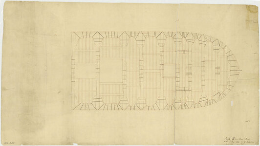
Maybe best is to show the problem in a photo of the drawing or even better with the model....
 
This is driving me nuts:). I'm doing the lower deck on the Discovery1789. According to the original drawing the deck beams are all different distances apart. It's in 1:48 but I'll use real measurements to maker it easier for me. The beams vary from 1" to 1 1/2" apart. The ledges have to have between 3/16 and 1/4" between them(not between centers). The ledges are 1/16" wide. Is there a method of doing the arithmetic to get the spacing even?
If you don't understand what I'm trying to say please tell me so I can try to explain better:)
Thanks

i will take a shot at trying to answer you

fist of all there is "model" ship building and "actual " ship building.
in model building builders will even out hull framing making the frames and spaces even, in real ship building both the frames and space will vary.
With deck beams builders assume the beams are all the same size and spaced at an even distance apart. That is not the case deck beams are set according to what is on the deck. In other words hatches, masts, deck house, etc some beams are larger than others if there is extra weight or stress on the beam.
look at this sample the deck beams are closer together at mid ship than at the stern, heavy beams are used to support the guns and all the beams are placed at hatches, mast and the companion way

carlings are place to frame in hatchways and to support various structures on deck. Ledges are placed at random and split the distance between beams.

The ledges are 1/16" wide. Is there a method of doing the arithmetic to get the spacing even?
i would say these is no set math to determine spacing it all depends on the deck structure.

js plan1.jpg
 
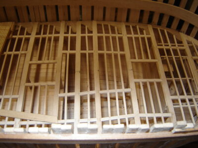
Thanks for the interest. I can't figure out what to take a picture of but I'll post this one. You can see the spacing of the beams are different. You can also see the dog's breakfast I made of trying to space the ledges evenly :).

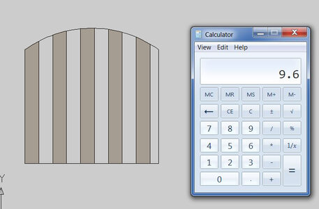
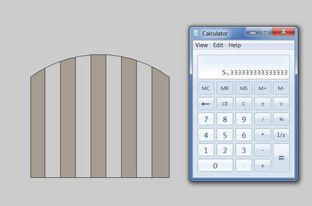
A good analogy of this would be building a garden gate. Say your posts are 48" apart and you have 5 "wide pickets. You want the pickets to have "about" 5" between them. How do you figure out how many pickets you need and how much space should there be between them? In this case there is a space at both ends like you're trying to fit the gate into a pre existing opening.DSC04394.JPG
 
A good analogy of this would be building a garden gate. Say your posts are 48" apart and you have 5 "wide pickets. You want the pickets to have "about" 5" between them. How do you figure out how many pickets you need and how much space should there be between them?

fence.JPG

ok the gate is 48 inches wide and you want pickets 5 inch wide and a space 5 inches wide. $8 divided by 5 yoy need 9 pickets with a smaller space about 2 3/4 inches

fence1.JPG

if you want an even width of the pickets and space 48 divided by 9 and each picket and space is 5 3/8 inches + or -
 
We were posting at the same time. Remember that with the ledges we need a space at each end rather than a picket as you have it.
I'm going over your method now.
 
What I normally try to do in this situation is start at one end and work to the other measuring distances and spacing as I go. This avoids trying to calculate spacing. The deck beams will then space according to the plan set. For modeling there is a plan b of sorts…simply calculate even spacing to the centers of each beam. The problem with this approach is you end up with deck beams in the wrong place for deck features…especially hatch openings. This is why my preferred method is to start in the stern and place each deck beam according to the plans.
 
As you say, the beam positions are tied to deck features and I actually got those from the drawings from RMG. It's spacing the ledges that is giving me trouble. On the Discovery the beams are not equally spaced(at least on the lower deck) so there is no standard for ledge spacing.
 
I have been pondering your question and I think we are overthinking this. Placing the deck beams are the first critical lead in to the rest of the deck structures. Ledges are simply evenly spaced between the deck beam structures. Depending on width between beams would determine laying in one, two, or even three ledges. Multiple ledges are simply evenly spaced…a good “eye” for symmetry is all that is really necessary in my experience.
 
Last edited:
You're probably right. I discovered that even if I do all the math, transferring the measurements back to the carlings is very tough. If I do it by eye it turns out just as nice. It's easiest if there is an odd number of ledges. Put the first one in the middle. If there is an even number it's tougher to get the first one right. I have also discovered that the alignment seems to be more important than the spacing. At least crooked ledges seem to show more than poorly spaced ones.
 
I am also pretty sure, that the old shipwrights defined the space / distance between carlings and ledges based on the loads on the deck.
The deck loads mainly and also partly the structural loads were transfered from the deck planking into the ledges into the carlings and finally into the beams, which are founded on the frames - so all was defined by transfering loads into the structure. Timber was expensive and later also rare, (and also heavy) so I am pretty sure, that the shipwrights installed were necessary, but not more than necessary.....
Defintely it should be symetric to the middle axis.

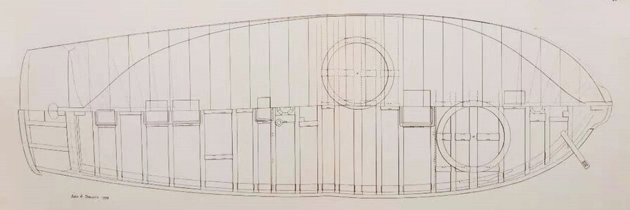
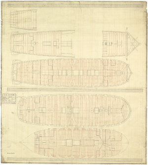
I know some contemporary drawings at the NMM which are showing the carlings and ledges very good, so you may want to take a look
j4283.jpg
Scale: 1:96. Plan showing the roundhouse, quarterdeck, forecastle, upper deck, lower deck, and orlop deck for an unnamed 1745 Establishment 60-gun Fourth Rate, two-decker. The plan illustrates the knees, beam, carlines (carlings) and ledges used to construct the decks. No specific ship is mentioned except an un provenanced note for 'Weymouth' (1752). However, it could refer to 'Anson' (1747), 'Saint Albans' (1747), 'Tiger' (1747), 'Weymouth' (1752), 'Medway' (1753), and 'York' (1753).


j8331.jpg
Probably 1:48. A plan showing the method of fixing the beams, knees, carlings and lodging knees for the forward half of the main deck of an unspecified merchant ship (fl.1797), as taken off by George Hilhouse in December 1797.

 
Thank you for posting these. I've seen the first one on MSW but the second is new to me. It's nice to see merchant ship drawings as the Discovery wasn't a Navy ship in the strictest terms. This one has opposed knees on the first eight (I think) beams. That seems very robust. I would have thought that merchant ships would have been built lighter than Navy ships. This seems to suggest I was wrong. Not the first time:) I'm assuming that the black lines are bolts. Do you know why some are dotted?
 
Back
Top