Stern Decorations - Hahn Drawings - Prototypes

Joined
Sep 5, 2017
Messages
1,689
Points
538

In this thread we will experiment and explore how to create scale 3D decorations for the stern of several famous ships. I have several requests to create parts for SoS members and their outstanding models so I figured I should show how it is done. I have been granted access to use some original Hahn drawings for the development of various prototypes of stern decorations. Through this series, we will all learn while I improve my skills so that I can provide SoS members the quality of parts they deserve for their models. With the collaboration of other members with CAD, 3D drawing, modeling, and other skills we can work to create objects that you will never see in production kits (with the exception of perhaps CAF and Trident). I also hope to add innovations never before used in scale modeling to push the technology forward. But I will need your help, critique and feedback along the way!!!

When we speak of fabrication technologies in general, there are two overall types: subtractive fabrication and additive fabrication. Subtractive fabrication is the process where material is removed from a larger raw stock to create the final object. Methods include: hand carving, sanding/shaping, CNC machining, and laser cutting. Additive fabrication is a more modern and expensive technology that involves adding material in layers to build up the final object. Methods include: 3D printing, Selective Laser Melting (SLM), extrusion, and injection moulding. Since my shop is equipped with traditional CO2 lasers and CNC machine, all of my discussions will center around subtractive fabrication.

Let us begin... our first series will focus on using a combination of laser etching and laser cutting to build up small parts in the creation of 3D decoration. The first example will be the stern of the USF Confederacy in 1:64 scale beginning with Harold Hahn drawings.

We want to build the parts in layers. Remember this is a prototype so we don't care to use good hardwoods. For the first sheet, we simply cut out the outline of the stern and windows from Hahn's drawings in 1:64 scale onto some 0.05" milled basswood. The sheet below took about 50 seconds on my laser.
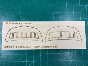
IMG_0263.jpg

The second sheet took more work inside my CAD software. Since we are just doing 2D laser cutting, I used CorelDRawX8 64-bit. My laser performs two functions. Raster Engraving - the head sweeps back and forth very rapidly just lightly etching the surface with fine details. And, Vector Cutting - the head moves slowly with a pinpoint beam of 60watt energy to cut right through the wood. Inside the software I differentiate the etching and cutting by the width of the drawing lines. Everything that gets vector cut has a width of "hairline" (less than 0.5pt pixel), while everything that gets raster engraved will have a width wider than "hairline". I spent several hours tediously going through the drawing to edit these differences. But once done, it is done. I then placed a sheet of 0.10" milled Alder onto the laser and sent the job. I apply a mask to the wood to reduce the char. In the picture below you can see the laser performing the Raster engraving function.
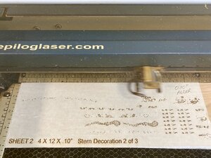
IMG_0265.jpg


Once the engraving is complete, the laser performs the Vector Cutting. My laser uses a jet of compressed air at 30psi directed at the point of the laser to immediately cool the surface of the wood. This prevents flame blow through on the backside greatly reducing burn on the back of the part. The completion of this entire sheet took about 10 minutes. My new laser is about 4 times faster than this one.
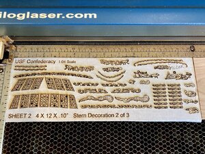
IMG_0266.jpg

Once completed, I carefully remove the billet from the laser, apply masking tape to the back-side of the billet to keep the parts in place. Then, I carefully remove the mask from the front of the billet revealing the parts.
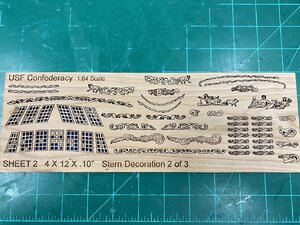
IMG_0267.jpg


On closer inspection, you can see the detail is very good. However, this is only the very first prototype. We can do much, much better than this. You will also notice there are no tabs on the part. Upon removing the tape from the back-side of the billet the parts will easily fall right out.
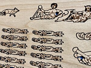
IMG_0268.jpg

This is only the beginning my friends. I also have stern drawings for Druid, Cromwell, and Rattlesnake. In addition, we will also be doing similar work but with 3D CNC carvings.

I welcome your feedback and questions. This is a huge topic.
 
Last edited:
Thank you all for the interest. We have one final sheet for the Confederacy stern decorations to fabricate.

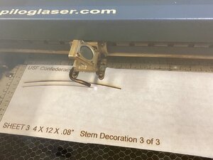
Unlike CNC machines, lasers do not require the material to be clamped down. There is no mechanical machining involved. The only thing removing material from the billet is the laser beam itself. Since the laser is "light" and light has no mass, there is no pressure on the billet of wood. In any case, all Epilog lasers include a vacuum hold down that actually pulls the sheet wood down onto the honeycomb tray. The shape of this tray allows the laser to cut directly thru the wood without burning the other side. It also allows debry to fall through onto a catch tray. The laser is actually shot from the side of the unit and then reflected at a 90 degree angle via a mirror and then focused through a lens. I have different size focus lenses for different job requirements. The bent tube you see is where the 30psi of cooling air blows onto the material surface.

IMG_0272.jpg

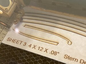
This laser is only 60watts. However, that is EXACTLY what we want for custom model fabrication. Higher powered industrial lasers cannot raster engrave at the fidelity we need for model building. The model laser in these photos is capable of etching at a resolution of 1200 dots per inch (dpi). However, all the etching you see for our Confederacy is "only" running at 300dpi. My new laser can etch at 2400dpi.

IMG_0273.jpg


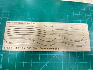
Here is sheet 3 of 3 done on 0.08" milled Alder. Only took 4 minutes as there is really not much work for the laser to do here.

IMG_0274.jpg


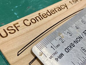
As a model builder of more than 50 years, the most important thing to me about any manufactured part is "fidelity of detail". Take a look at how crisp these parabolic cut lines are. Only 300dpi. There is alot more to come my friends.

IMG_0275.jpg
 
Are you planning to make these decorations for Rattlesnake 1-48 as well, very exciting, I follow the development of these decorations, thank you-
Thank you for the nice comment. Rattlesnake is on the list. The priority at the moment is to demonstrate various techniques for creating 3D decorations via both laser and CNC. This will be a progressive thread where we will get more advanced as we go. Regarding SCALE - everything you see here can easily be sized to any scale you might need within reason. By that I mean, if you were to ask for 1:96 scale, a lot of the small detail would be lost of course. So, the larger the scale the higher the fidelity of detail. My personal favorite scale to work in is 1:32 but really there is no limit - it is just math.
 
as a CAD draftsman i have to be able to create drawings that are workable and to do that i need to understand how the laser software sees my drawing.

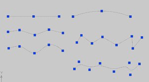
top left is a line simple the laser knows to go from point A to point B

next is a series of lines i can create that with lines or polylines and then edit the polylines into one object

next is a spline and like the above poly lines the spline will used the points and create a smooth curve

to the right

a simple arc cad will create and arc from the 3 points

next a polyline and below it is a polyline that has been edited, you can see the same points where CAD used those point and created a smooth curving line. other programs may or may not see the editing the same as CAD

points3.JPG

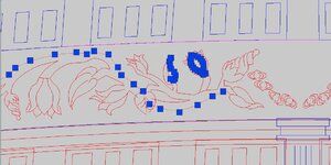
doing a detailed drawing it may take all the above types of lines to produce the object. You can see in the little bud the amount of points. In a final drawing there could be hundreds of these points.
Does a laser start and stop at every point?

points1.JPG

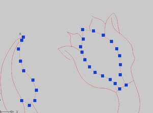
zooming in on that bud which is only a small part of the drawing and you can see how many point there are. The overall drawing of the vine can have a couple hundred points how does this affect a laser if at all.

I have done drawings and sent them off to a laser cutter and they told me the sheer amount of data is choking the laser, it can not deal with that amount of points


points2.JPG


We have a number of CAD people here on the forum so knowing how to do a drawing that can be cut is a good thing to know
 
Does a laser start and stop at every point?
I have done drawings and sent them off to a laser cutter and they told me the sheer amount of data is choking the laser, it can not deal with that amount of points
We have a number of CAD people here on the forum so knowing how to do a drawing that can be cut is a good thing to know

Great observations, comments and questions Dave. I will do my best to explain so that everyone can understand.

Let's start by looking at laser "cutting" versus "etching" as it is easier to explain. As we said earlier, the process is known as Vector Cutting - the laser follows a drawn line defined by the CAD or drawing software to cut through the wood. As Dave points out, this line can be defined simply by 2 connected points, many connected points, or in-fact thousands of points that are not even connected but look like a line from a distance (bitmap). One of the most tedious tasks for a fabricator is taking someone's drawing and discovering the lines are made up of many unconnected points, disconnected lines, lines on top of lines, extraneous dots (pixels) that are not part of the line, etc. We call these Open Vectors (i.e. not contiguously attached). Open Vectors are often the case when the drawing is created with low-end, freeware, or open source software that does not include advanced Vector Checking functions. As the head of the laser moves, it will skip over the spaces (pixels) where the lines are disconnected. For extraneous dots the laser will simply shoot a single pixel sized hole right through the wood. You will see these Open Vector errors in kits where you notice the part does not want to release easily from the billet and you have to cut it out. If you flip the laser cut part over, you may see tiny little dots where the line should be cut. These are Open Vectors - not good. When I find someone's drawings with Open Vectors, I use my CAD software to close those vectors by joining the dots together into a properly flowing continuous line or shape. Then I run a Vector Integrity Check to ensure I have no Open Vectors. Depending on the original drawing this work can take hours and hours to perform. The only time there needs to be a gap in a laser cut line would be to provide for a "tab" to keep the part in-place inside the billet. Tabs are a traditional method carried over from CNC that allows parts to be shipped inside the billet without fear of damage. Nearly all kit manufacturers use Tabs on their laser cut parts. As you know, these tabs have to be sanded off the parts. I do not use Tabs in my laser part fabrication. Instead, I back the parts billet with masking tape to hold the parts in for shipment. Much higher quality, much easier for the model builder.

TIP: For those of you creating drawings for Laser Vector Cutting - Close all of your lines with "joins" into a single continuous line, then group it into a single object. You also do not need to draw tabs. This will reduce the workload on my end and ensure a much better product in the long run. Also make sure you do not have duplicate lines on top of lines. If you do, the laser will cut the same line twice creating a loss of detail and excess char.

Ok, now for Laser Raster Etching. As we said earlier, this is where the laser head sweeps back and forth rapidly to etch an image on the surface of the wood. Instead of following the path of a vector, the laser is actually firing thousands of times per second and etching each and every dot (pixel) that is defined in the drawing at whatever resolution we have set for the laser. So at 300dpi, the laser is firing 300 dots per inch as it sweeps. At 1200dpi, it would fire 1200 dots per inch. The only difference is the size of the dots. The source drawing is not as problematic for this function as it is for Vector Cutting as the software is simply going to render whatever is in the drawing onto the wood. However, if the source artwork/drawing is of a low resolution the final output from the laser will also be low resolution. In other words, the etching will be as good as the original artwork. Junk in, junk out. While it is true that some CAD software and lasers will fill up their memory buffers with data when trying to render complex drawings you will NEVER see that with my equipment.

TIP: For those of you creating drawings for Laser Raster Etching - Create artwork as detailed and at the highest resolution you possibly can. I can take it from there and render it beautifully onto wood. If your drawing is basic, the result will be basic.

I hope this helps explain a very technical topic. Any and all questions are welcome!!
 
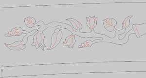
this CAD drawing is set up to cut different ways the black line cuts through and the red lines are etched

so by changing the colors of the lines can you change the laser settings for each color?

the leaf in the lower left has red lines that start and end so at the end of the line does the laser search for another line? Those red lines are "dead ends"
Will the laser look for the next line that was drawn?

if the laser is cutting in the order the drawing was done it might cut one line in the leaf then skip all the way to the right and cut another line then skip to someplace else

point4.JPG
 
this CAD drawing is set up to cut different ways the black line cuts through and the red lines are etched
Good stuff Dave and this helps push our topic along. As we discuss this let us understand I am referring to my Epilog lasers and how they function. These are high-end commercial lasers designed specifically for modeling and high resolution commercial art. So all of my description are based on how they work and may not reflect the function of industrial or consumer type lasers.

so by changing the colors of the lines can you change the laser settings for each color?
Your CAD drawing where the black lines define Vector Cutting and the red lines define Raster Etching are perfectly fine for you and I. However, the color of the line is not how the laser decides whether to cut or etch. This determination is based on the width of the line. Any line that has on outline width smaller than 0.5pt, also called "hairline" will be Vector Cut by the laser. Any line that has an outline width 0.5pt or larger will be treated as a graphic and Raster Etched. So in the case of your drawing, I would import it into Corel Draw, select all the black lines and set the outline width to hairline. Then, I would select all the red lines and set the outline width to 0.5pt, or I would leave them original size if larger than 0.5pt. If you want to, you could save that step for me by setting those line sizes as your are creating your drawing. Unfortunately, not all software has the functionality to adjust line widths down to hairline size... so it just depends.

if the laser is cutting in the order the drawing was done it might cut one line in the leaf then skip all the way to the right and cut another line then skip to someplace else
Epilog lasers are extremely intelligent and super efficient. When a job is sent to the laser that contains both Vector Cutting and Raster Etching, the machine will optimize the order to make best use of the hardware. In general, the laser will first sweep from bottom to top Raster Etching all artwork in the job. It will automatically skip over any areas of the board that has no artwork. Once the etching has completed, the compressed air cooling jet will kick on and the laser will Vector Cut all lines defined as hairline in the most efficient, continuous, mathematical, fastest order the Epilog software determines. Has nothing to do with how the original artwork was drawn.

The reason I said "in general" is there are certain variables we can adjust.

For Raster Etching we are able to define the speed at which the head of the laser sweeps (1 - 100), the power the laser emits (1 - 100), the direction of etch (top-to-bottom, or bottom-to-top), resolution in DPI (75 - 1200), and Dithering. After years of experience, I adjust the speed/power based on wood type, I run my direction bottom-to-top as this results in smoke crossing the surface only once, I usually use either 300 or 600DPI, and for Dithering I run Stucki on wood and Jarvis on Glass.

For Vector Cutting we are able to define the speed, power, and frequency (0 - 2500Hz), and vector sorting order. For me speed and power is determined by the type and thickness of wood, frequency is always 500Hz for wood, and I set vector sorting to "Optimize".

Regarding your "dead ends" on the red lines. Does not matter as these are Raster Etched. We only need good connected and closed vectors when we are cutting.

I know that was a long explanation but it is a complicated topic and may help folks who like to do drawings and see them turned into actual model parts!!!
 
Last edited:
So check out this short video one more time from a couple years ago when DocBlake and I were working on the Jeff Staudt Battle Station. You will first see the laser Raster Engrave(Etch) the title and then it will come back and Vector Cut out the stair steps...

Should help everyone better visualize what we are discussing above.

 
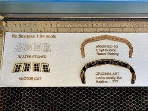
Ok, let's look at the example above a bit closer. Below we have stern windows and artwork from the Rattlesnake.

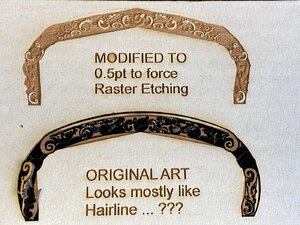
The stern windows in the upper left have been Raster Etched with a 0.5pt line width, while the exact same windows below were Vector Cut simply by changing the line width to "hairline" (less than 0.5pt). The artwork on the right is a bit more troublesome. The original work on the bottom had a combination of line widths to include many hairlines. The result was a mess. In the upper right I selected the entire drawing and modified the entire thing to 0.5pt to force Raster Etching. The results were better but not what we would want on a model.

IMG_0277.jpg

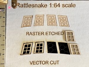
A closer look at the windows and you can see the nice Raster Etching in the upper picture even in the soft basswood. The lower pictures have the windows cut out via Vector cutting and once the mask is removed they look pretty good. Although this is 1:64 scale we could easily make them in any scale.

IMG_0279.jpg

Windows and other structural parts are one thing, but when it comes to actual artwork both the original artist and the fabricator need to work together to reduce the amount of time required to create the best parts. As we can see below, neither result is good enough for us. A lot of additional time will be needed to update the original drawing so that we can get what SoS builders deserve. The nice thing is, once its done... its done. And again - any scale... no problem.

IMG_0278.jpg
 
Back
Top