
Great work on the transom!

You are using an out of date browser. It may not display this or other websites correctly.
You should upgrade or use an alternative browser.
You should upgrade or use an alternative browser.

Decided after several unsuccessful tries -"foot " too narrow , too short, not covering ends of transom well- that I need to stop and rethink. Distract myself by making shelf for tilted shelf of disc sander- close gap and non slip for small pieces( thin platform or wood, edge cut to same degree as table and sand paper cover). " Change is as good as a rest"'
Double checked all heights and angles against plan. All ok. Suddenly the penny dropped- I was cutting the under bevel at the foot FROM rather than TO the dotted line. Made up another attempt - it works. STUPID me - and wasted nearly 4 hours. Spot glue foot to step alongside fashion piece. Doesn't perfectly match the ends of the transoms YET, but TFFM mentions overlap. Also difficult to see at what point it meets the tip of the wing transom i.e. how far "out". **CAN ANYONE ADVISE** I cant see any reference on a frontal plan. It aligns with the angle of aft cant as per breadth plan. I intend to make its opposite no. to check symmetry before final gluing. (After so many mistakes, I made in one part and faked the chock. I will try the starboard as separate sections now I know where I went wrong)


Double checked all heights and angles against plan. All ok. Suddenly the penny dropped- I was cutting the under bevel at the foot FROM rather than TO the dotted line. Made up another attempt - it works. STUPID me - and wasted nearly 4 hours. Spot glue foot to step alongside fashion piece. Doesn't perfectly match the ends of the transoms YET, but TFFM mentions overlap. Also difficult to see at what point it meets the tip of the wing transom i.e. how far "out". **CAN ANYONE ADVISE** I cant see any reference on a frontal plan. It aligns with the angle of aft cant as per breadth plan. I intend to make its opposite no. to check symmetry before final gluing. (After so many mistakes, I made in one part and faked the chock. I will try the starboard as separate sections now I know where I went wrong)

Hello stuglo, looks absolutely great.
What is the difference between OCD and perfectionist? I'm the latter of course!
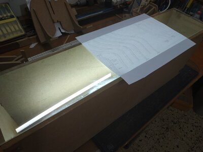
Well, still not happy with result. Rechecked again and found the professional printer had made a 0.5% error. Doesn't sound much but with a compound curve the effect is obvious. This time I copied rather than print/save- accurate. Now try an alternative - the integral chock. Allows some "flexibility" with ability to rotate upper half. Also bit more adventurous than single whole part (snobbery). For starboard side, need a "reverse "plan. The "flip" on the computer is still not accurate. My ability with tracing paper is somehow inadequate, but !!inspiration. I'll build a light box . No patience or ability to obtain materials (Corona shutdown).
Then !!! further inspiration- photo frame +its glass resting on upturned lamp. It works.
I've left the cants a bit fat at level of wing transom and above. NOTE- keep spaces in place while gluing.
The plan is fixed to the vertical guide plate of the building slip- initial eyeballing looks good. Leave finishing until after next cants are built.

Very clever idea with the lightbox Stuglo, I might use that idea in future myself.
Looking forward to the rest of your build.
Looking forward to the rest of your build.
I should be leaving the aft cant and moving to the stem and the Ballard Timber or knightheads (which sound much better). Opportunity to clear the decks (working space). Then print ACCURATE copies of the parts.
One of the disadvantages of the building slip, is the difficulty in lying the plans flat and alongside the keel. I reviewed Kevin's video and realised I'm not alone in my struggles in understanding and skill limitations. He also emphasised the need for accuracy with the aft cant-being fundamental to prevent accumulative errors. So I checked again,first levelling the plan by puting (temporary) some MDF offcuts under the otherwise unsupported parts of the plan.
LUCKY- using the square, I found the transoms had rotated on the stern -despite or maybe because I used thin copper tunnels rather than wood. I Had used a rubber band on one side to maintain a tight fit. Mistake. Rule- what you do to one, do to the other side.
Unglue with alcohol (70%) + hair dryer (can't get 90% as restricted to house)- All came apart ok. Realign with temporary glued "stays" from wing transom to back of slip to prevent unwanted movement. Tomorrow I intend to check again before reattaching aft cants and see if they need altering.
Time-consuming and frustrating, but better now than later. You're supposed to learn from mistakes, but I still feel stupid.

I love your way of working - very pragmatic ..... great and very Coooool 
Checked after "stabilizing"-some correction needed. Used a sanding pad (foreground)-one of the few times I've used a normal DIY tool for modeling. Small sanding pads or sticks tend to cause some curvature .
Again move on to Timberheads. Very complex. Each step at a time.
Blanks of 6.36mm
As advised, checked print plan against rabbet on either side. By some miracle they match!!!
Even so I cut (band saw) and finish with band sander and spindle sander. How people did (and still do)this work by hand tools is amazing. On the other hand they acquire skills which I will lack.
There are 2 parallel lines near the top that represent the recess for the bowsprite. These are good for points of reference.
We are now in relatively strict shutdown- my professional printer is closed. I realise that I will continue to need many reverse (flip) copies of plans of parts.
I have been unable to do this to correct size with my cheapy HP (CAN ANYONE HELP WITH A SOLUTION)
My quicky light box is too limiting
So made a new one.
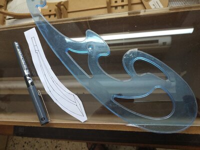
Some MDF packing ends I found in street some months ago (always on look-out for potentially useful stuff) . Cut it to 70cms length. Fitted an old 60cms fluorescent light and covered with some leftover 4mm perspex.
It works. I also get to use some french curves that I've had for many years and never used, to mark the reverse of the plan. Much more accurate.
Back to Timberhead.
First bevel- at heal facing outwards. Sounds obvious , but mark which side-port or starboard. Note this angle is now 34.5. SO REMEMBER TO CHANGE THE ANGLE of the sander or saw you are using.
Next step took some understanding because used to thinking in fore-aft or horizontal curves, but then I realised that this step means shaping the inner face of the part as it lies flat against the deadwood/apron. These parts , with the keel, were previously narrowed towards the keel. To allow the timberhead to stand vertical, it must be narrowed towards the top.(This is how I understand what to do and where to do it -I may be proved wrong in the next few pages)
First cut a small acute recess in the fore of first step to allow slight insertion of aft foot tip of timberhead).
On my model, the widening of the stem going upwards, is from 6.22 to 7.24mm. The amount to be removed from EACH timberhead graduating to 0.5mm at the top. (each timberhead,0.5X2=1mm) Sorry to be obvious again, but I almost took the whole difference from the first side. Thus the combined width of deadwood +2xtimberheads is same all the way.(these numbers allow for paper thickness.
I made this gradient using a sanding board and varying place of finger pressure a


Again move on to Timberheads. Very complex. Each step at a time.
Blanks of 6.36mm
As advised, checked print plan against rabbet on either side. By some miracle they match!!!
Even so I cut (band saw) and finish with band sander and spindle sander. How people did (and still do)this work by hand tools is amazing. On the other hand they acquire skills which I will lack.
There are 2 parallel lines near the top that represent the recess for the bowsprite. These are good for points of reference.
We are now in relatively strict shutdown- my professional printer is closed. I realise that I will continue to need many reverse (flip) copies of plans of parts.
I have been unable to do this to correct size with my cheapy HP (CAN ANYONE HELP WITH A SOLUTION)
My quicky light box is too limiting
So made a new one.
Some MDF packing ends I found in street some months ago (always on look-out for potentially useful stuff) . Cut it to 70cms length. Fitted an old 60cms fluorescent light and covered with some leftover 4mm perspex.
It works. I also get to use some french curves that I've had for many years and never used, to mark the reverse of the plan. Much more accurate.
Back to Timberhead.
First bevel- at heal facing outwards. Sounds obvious , but mark which side-port or starboard. Note this angle is now 34.5. SO REMEMBER TO CHANGE THE ANGLE of the sander or saw you are using.
Next step took some understanding because used to thinking in fore-aft or horizontal curves, but then I realised that this step means shaping the inner face of the part as it lies flat against the deadwood/apron. These parts , with the keel, were previously narrowed towards the keel. To allow the timberhead to stand vertical, it must be narrowed towards the top.(This is how I understand what to do and where to do it -I may be proved wrong in the next few pages)
First cut a small acute recess in the fore of first step to allow slight insertion of aft foot tip of timberhead).
On my model, the widening of the stem going upwards, is from 6.22 to 7.24mm. The amount to be removed from EACH timberhead graduating to 0.5mm at the top. (each timberhead,0.5X2=1mm) Sorry to be obvious again, but I almost took the whole difference from the first side. Thus the combined width of deadwood +2xtimberheads is same all the way.(these numbers allow for paper thickness.
I made this gradient using a sanding board and varying place of finger pressure a
Attachments
Sorry to return to the problem of position and symmetry of aft cants. The vertical plan holder supplied with the building slip is "solid" and does not allow to be close to the "arms" of the cant from in front because of te deadwood and protruding lower part of cant. The system holding the stern must be removed to allow it to be close from behind. In which case the stern cannot be held still. When there is distance between part and plans, I (and maybe others) have a major problem with PARALLAX- distorting alignment. A solution is a "bridge" from either side and over the building slip. Rather than spend time making something in wood, for a quick fix I "borrowed" some of my grandchildren's building blocks that we keep here. It works.
Back to the timberheads:
Because these pieces are going to be repeatedly offered up to the stem while forming them, I aligned the pair and (using a drill press to ensure 90deg) made a hole to allow a pin to loosely connect connect them. With just one side correctly position, I drilled through this side and through the stem -the pre-existing hole acting as a guide. The pin then connects the 2 sides and stem quickly without constant adjustments.(seen in picture with clip at one end).
Again check they sit vertical and parallel (widening of stem compensated by narrowing of timberheads) . TFFM suggests a combined width of 18.3 but a tolerance of .26 mm OK. Mine is 19mm- as I tell my wife, I'm just too tolerant!!
Check my post on modifying the Building Slip. I've been singing its praises but nothing is perfect (except my wife of course) . Apart from a stable bridge I've changed the keel clamps to allow access to breadth plan.
Return to timberheads.
Need to bevel forward faces .Keep in mind how the planks lie to ensure remove right side- then mark it.I have no confidence in my ability with a chisel (as recommended in TFFM) but use combination of table belt sander, hand held belt sander, small sanding block and a final knife scaping to flatten the curved surface that my sanding tends to give. Note- suggests a narrow margin is left (illustrated in book).There is another (smaller) bevel on the opposite-inboard- side. Check multiple times that the wood you propose to remove coincides with direction of future planking.Looking under the "foot" should give a rhomboid shape.
TFFM then speake of a small step (1.3mm) that suggests can be postponed. Good, because I don't understand what is to be done. Referring to the 3D, I see something, but am not sure if this is it.
The next step looks complicated , delicate and slow- and the Bosun suggests I need to fix the toilet cistern -oh s***.
Moving on to the air spaces. Almost made mistake as the text says make it BELOW the hawse hole but the drawing seems to me to show those above. The amount to be removed is a thickness of 0.4mm. Allowance must be made for the gradient created when the piece was previously thinned . Chisel is again the suggested method but I will again postpone this until I acquire the necessary expertise and mess up a piece that I have not invested so much time.
Set up for milling with a thin wedge to compensate for the height difference. The starting line is marked by small "v" on plan. Start the milling just below this so that later a 45deg downward sloping cut can be made with a blade. I use a small Proxxon MF70. I have limited experience but it seems adequate for my needs. The shape of the part requires repositioning one of the clamps. This done, I lowered my bit the 0.4 mm and switched on without realising I hadn't needed to raise it to re-site the clamp. Fortunately I hadn't touched any directional wheel and the bit was only 2mm. Must have been the evil-eye of the chisel gods, Finished the job, putty mix with sawdust and watery PVA and almost invisible repair. (It's in a place that will be hidden but I know).
2 loose holes for pinning pair of pieces in place. One already in foot, the other above the air space line. For accuracy use drill press (90deg) and holding one piece correctly positioned, the hole will guide the drill bit as 90deg through the stem. Except I hadn't allowed for the thinness of the overlap and it simply missed the stem. Redo near fore edge. The extra hole get the putty treatment.
**Two stupid mistakes in quick succession require immediate cessation of building activities. Usually lack of concentration or bad luck- doesn't matter. I remember reading a book on playing bridge by S.J.Simon many years ago- if things go wrong, get up and walk away. Tomorrow is another day. I'm too embarrassed to post any pictures.
In 1980 I was involved in medically examining English athletes for the Moscow Olympics (which they subsequently boycotted). This is where I first learned about the importance of visualization to perfect physical activities. (when I was younger these were called fantasies). The relevance to those model building will be apparent when I tell you I awake in the middle of the night planning how to do something. This was especially true when considering the head of the timberheads. The simple method of shallow saw cut and shaping is prevented by the parallelogram effect and backward slope. In past models I must have missed this or fudged it. Checked out Kevin's video -at first this upset me because my small table saw's blade is of fixed height. The middle one, blade to thick and not as yet built a sled. Fortunately he later discards this method (Phew!!!). At least reminded me to use some trial pieces. The medium saw was inaccurate in at least one of the dimensions required then-lightbulb moment- my dividing attachment for the proxxon milling. Used vertically, it will rotate the head to compensate for the parallelogram. Not enough, as about to return to some free hand work, I thought -what if I slightly rotate the attachment to match the slope of the stem. The narrowing of the piece as is rises upwards is not a problem over such a short distance. Trial piece not so successful but I can see this is a solution. Drawing at a larger scale, calculating the spacing and depth of cuts and using 1mm bit. I commit myself. Just remember to double check which wheel you need to turn and which direction. Eyeball the end of the piece to check they are horizontal to the table. Working each side, firstly fore aspect, I removed 1mm down at depth 0.3mm, another 1mm at depth 0.5, 1mm at .2mm and final line a further 4mm at depth 0.5. Rotate piece within the attachment 180deg. Starting from top, this first past should be about 0.5mm further down- fitting the slope to aft of stem. Repeat previous steps. Now rotate 90deg and releasing the holding nuts, the attachment can be angled to follow the slope. Double check the direction of the angle allows it to run parallel and repeat the same sequence of cuts. Rotate 180deg. and change direction of holding attachment to opposite and again follow line of slope. Its sounds complicated reading this but it is quite simple.
I took Kevin's idea and used the mini proxxon sander P13 with barrel head and it shapes the widest gap quite well. I was less successful with the mini files and sanding. Not completely satisfied . Maybe later on remove top bit and refashion. The problem is seeing the 3D and the great craftsman on this site makes me want better for myself.


I took Kevin's idea and used the mini proxxon sander P13 with barrel head and it shapes the widest gap quite well. I was less successful with the mini files and sanding. Not completely satisfied . Maybe later on remove top bit and refashion. The problem is seeing the 3D and the great craftsman on this site makes me want better for myself.
7th oct. Not posted yesterday because after 4 or 5 hours of thinking , planning and trying to understand the complexity of the mortise and bridging chock, I had little to show.
TFFM suggested earlier the making and use of a sanding cylinder riding up and down a rod extending to the keel (station 3)such that it forms the correct angle to form the slope of the stem top. Remembering the bowsprit is 9.8mm , the top of stem , inner timbers and bridging chock make up quadrants to encircle this.
While clamped to stem mark lower level of this groove on inner aspect of each timber where it meets upper lip of stem (it slopes).decided to start on the chock.Remove parts and just above this line , start making the grove. I used a 6mm round file to start then enlarged with sanding drum-keeping to the angle and margin of the slope .The depth suggested is about 1.55, leaving ,in my case,4.0 of the timber at its narrowest. Reassemble onto stem then use the sanding stick. *I overdid this, and a small sliver was left gluing overnight as the resulting hole for the bowsprit would have been too large .
While waiting for this, and having the grooving tools to hand I thought to start the chock.
A small block of 6.36 is suggested. The same groove is made at the angle of the bowsprit slope (as I will now call it), which is also the slope of the underside of the chock going aft. This I tried to do but the result was a fan shape looking backwards because these slopes didn't match. Have to sleep on it
I suppose most of us like/need drawing the task at hand by way of deconstructing or reverse engineering and so understand what to do and visualise the result. I use the numbers, if only approximate, to help ,especially drawing larger scale to fill in the missing information (usually that I missed or forget). Given the front minimum thickness of chock, the aprox. angle 20, I can see the aft thickness.
Yesterday's failed trial with sloping groove set me thinking to different approach.
Abandoning the 6.36 block, I took one 9.3 X30X30, made the groove horizontal, across grain, and the, turning the block over and slanting flat underside (will be upper side ) to 20angle, milled this horizontal, so the groove (with its uniform depth and parallel sides) now becomes a 20 deg. slope. Front and back are now sanded to 90deg to top.
The depth of the piece is now sawed in half. The second half can now be placed upturned spot glued a sides, forming a squared piece for easier working.
The extra depth is important to allow for the "wing" effect (as seen from above)
While this is drying, return to groove of timbers, clamp in place and with greater care and using the sliding sanding stick, form them more accurately.
Removing the timbers again, lay on plan and mark high point of the underside of uppermost rail- the second line 11.5 below top of timber. This is the upper mortise line. HORIZONTAL -90deg to timber. It is on the INNER aspect of timber. According to Kevin 2mm deep. I commit to a chisel at last. Masking tape to set depth of cut. Tap Tap Tap with small hammer. IT WORKS. Terrified I will decapitate the head but its cross grain. More confident, trapping the piece with fingers (behind) I push from lip of grove, angled slightly downwards , towards cut and remove slivers until clear to base of mortise cut. Seen from front or back, the result is a right -angled triangular gap. Treat the other side, and when held together they become an isosceles triangle. Again, the point of the angle is the upper lip of the groove. Very satisfying. The chisel blade prevents the convex that tends with sanding small pieces by hand.
Back to the chock.
The (temporarily) combined piece can sit flat and the diagram in TFFM of the view from above can be transferred (traced) Note again the wing shape. Overall depth requires at least 6.6mm. The pieced is shaped with the wings overlong. The two piece are now seperated.
The flat top is thinned slightly so the thinnest part above the groove (hopefully the centre) is 2.65mm
Now for the fun.
The with of the stem at mortise is 7.8mm
Each side the upper mortise is 2mm deep, giving total 9.8mm
The lower end is 0.0 Lucky with chisel already, but I won't push it, I use the hand band sander to make the bevel by stages -parallel fore-aft sloping down. Firstly with the timbers separately on the work table to check angles and fit, then offered to them when clamped to the stem until touch by touch, the fit. When sure and satisfied, glue.
To misquote TFFM and Winston Churchill "Never in the field of ship modelling has so such time and and so much effort been to produce a piece so small" (Not true of course)

Cleaned up bridging chock to blend with bevel of timberheads- looks OK to me.
Ist Fore Cant frames:
Referring back in TFFM-"all cant frames are 9ins"- 4.77 mm in our case.
After experience (not so happy) with half chock aft , I'm going to cheat , do it as I piece and simulate the chock.There will be many more opportunities to make to make chocks, but the house pieces depend on the accuracy of this piece.
Made an extra wide blank to accommodate this, as well as some trunnels for fixing glue parts -wood rather than copper or nylon more appropriate.
The UNDER bevel at the foot is at 34.5deg. It sits on 1st step behind a will also be glued to the foot of the timberhead.
Make in usual way - stick cut outs both sides, under bevel by angled disc sander etc.Make faux chock marks. Remember to mark port and starboard parts to be removed when bevelling.
Offered as dry fit and PANIC! Not suitable aligned to breadth plan. Remember previous problem and realised the keel had moved slightly backwards. readjusted and fits OK. Constant use of square or similar is essential to make sure this alignment remains correct to this breadth plan while gluing. Must also view against the body plan and , as stated, outside distance at level of timberline (marked on plan) is 6.89 -that is 3.45mm from centre line of plan. Not so easy, but if bevel angles are accurate, it works.
(Don't trust the markings, use a protractor or similar every time.)
While glue drying double check all aspects and place the trunnels for extra security against movement.
The building board is 100cm and must be rotated frequently to attend both sides. My work table is only 70 cm . It was bound to happen- during a rotation the aft cant hit my arm. IT was guilty. Anyway separated at joint and needs repair. View attachment 184713View attachment 184714View attachment 184715View attachment 184716View attachment 184717View attachment 184713View attachment 184714View attachment 184715View attachment 184716View attachment 184717View attachment 184718
Hawse piece #2
started this yesterday-
The TFFM advice is detailed and again I appreciate the amount of work and expertise involved in preparing this.
Blanks of 7.95 are prepared -the angle of bevel remains 34.5 (but check anyway). In order to compensate for the air spaces, spacers of 0.4 and 0.8 are prepared from slivers of wood and doubled card.
Some confusion as to which line forms the base of the bevel, but its the one that is perpendicular to the keel and abuts the fore aspect of 1st cant.
The beveled piece should now fit nicely between the cant and foot of timberhead. Port good, starboard not so. Despite fixing and checking there has been some shift. I avoided clamping and used trunnels, but in any case the joint isn't straight.
Separate with alcohol, refit and restick.
Today:
The cant seems to be OK.
Next problem is how the hawse #2 sits against the timberhead, ? height ? forward extension.
When taking height of opening from plan, the piece sits too low. Align height of air space (marked on plan) and top of piece to timberline (height of bridging chock ) and opening 3.5 mm (about 7in real) lower. The book says go by the plan but why discrepancy? Should the position of opening define height/position of piece? I don't want the inner hawser hole to open into or beneath the deck!!
After 3 hours of thinking and remeasuring (exhausting) going back from the very first instructions and checking everything from the keel upwards it seems that the upper parts, tip of stemhead+1mm, top of chock +2.5 mm.
? where the error. Nothing dramatic, but the black paper (3 times) thickness of glue, maybe . The steps of the apron are about 2mm too high and aft end lower stem is 1.0mm too wide. These accumulate. I think a lack of experience and leaving too much margin is part of the problem.
***
The internal build will be according to plan. At this stage I don't think I need to start again. If necessary I will adjust my timberline (slope above fore cants) when frames are in place. I would be very appreciative for advice on how to proceed.
***
something is not working with the photos of this post - maybe you edit and post them once more - Thanks in advanceCleaned up bridging chock to blend with bevel of timberheads- looks OK to me.
Ist Fore Cant frames:
Referring back in TFFM-"all cant frames are 9ins"- 4.77 mm in our case.
After experience (not so happy) with half chock aft , I'm going to cheat , do it as I piece and simulate the chock.There will be many more opportunities to make to make chocks, but the house pieces depend on the accuracy of this piece.
Made an extra wide blank to accommodate this, as well as some trunnels for fixing glue parts -wood rather than copper or nylon more appropriate.
The UNDER bevel at the foot is at 34.5deg. It sits on 1st step behind a will also be glued to the foot of the timberhead.
Make in usual way - stick cut outs both sides, under bevel by angled disc sander etc.Make faux chock marks. Remember to mark port and starboard parts to be removed when bevelling.
Offered as dry fit and PANIC! Not suitable aligned to breadth plan. Remember previous problem and realised the keel had moved slightly backwards. readjusted and fits OK. Constant use of square or similar is essential to make sure this alignment remains correct to this breadth plan while gluing. Must also view against the body plan and , as stated, outside distance at level of timberline (marked on plan) is 6.89 -that is 3.45mm from centre line of plan. Not so easy, but if bevel angles are accurate, it works.
(Don't trust the markings, use a protractor or similar every time.)
While glue drying double check all aspects and place the trunnels for extra security against movement.
The building board is 100cm and must be rotated frequently to attend both sides. My work table is only 70 cm . It was bound to happen- during a rotation the aft cant hit my arm. IT was guilty. Anyway separated at joint and needs repair. View attachment 184713View attachment 184714View attachment 184715View attachment 184716View attachment 184717View attachment 184713View attachment 184714View attachment 184715View attachment 184716View attachment 184717View attachment 184718