Swedish capital ship ca. 1700 – into the abyss of the Great Northern War

Joined
Apr 26, 2023
Messages
540
Points
353

Location
European Union
.​

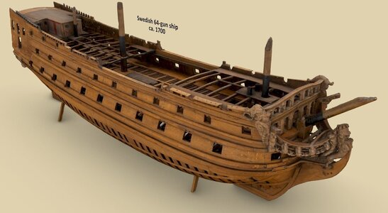
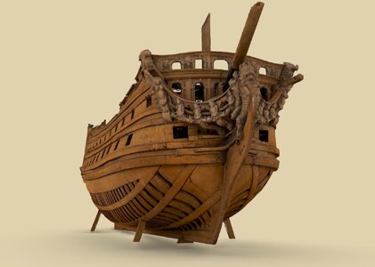
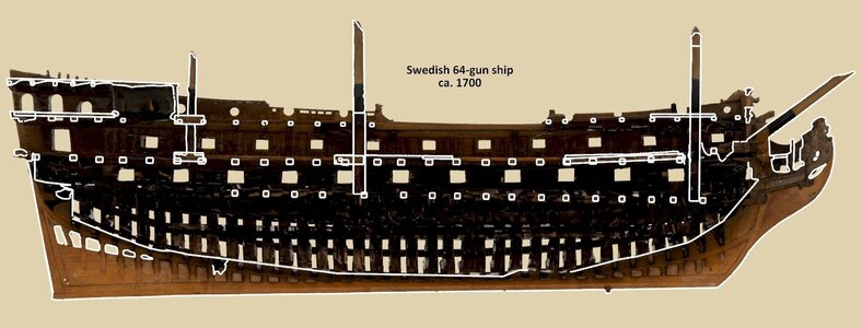
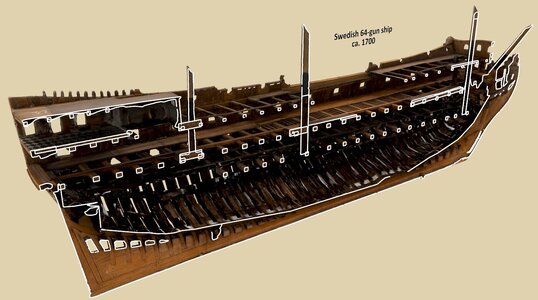
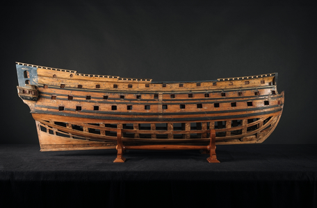
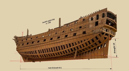
The very launch of this thread has been made possible by the kind decision of curator Jonas Hedberg to make a recent 3D scan of the hitherto unidentified ship model Ö 6 from the collection of the Sjöhistoriska museet in Stockholm available for download. More information about this promising model can be found on the museum's website:

Fartygsmodell - Sjöhistoriska museet / DigitaltMuseum

And on the Sketchfab website:

Ship of the line, c. 1700 | Linjeskepp, ca 1700 - Download Free 3D model by SWEDISH NATIONAL MARITIME AND TRANSPORT MUSEUMS (@maritima) [3afea35] (sketchfab.com)

Many other relevant data, particularly useful for the identification of the model, can also be found in the major studies on the Swedish fleet and shipbuilding: Svenska Flottans Historia. II. 1680–1814. Örlogsflottan i ord och bild från dess grundläggning under Gustav Vasa fram till våra dagar, Malmö 1943, Svenskt skeppsbyggeri. En översikt av utvecklingen genom tiderna, Malmö 1963 and Karlskronavarvets historia. Del 1. 1680–1866, Karlskrona 1993.

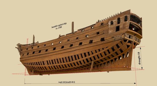
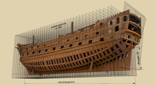
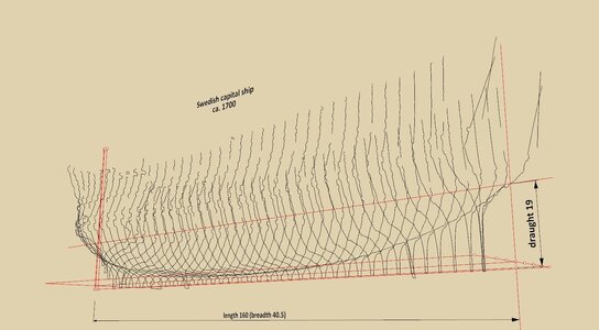
Some views of the model Ö 6:


ViewCapture20240502_234800.jpg


ViewCapture20240502_235615.jpg


ViewCapture20240502_234546.jpg

ViewCapture20240503_001523.jpg

.​
 
.​

Thank you Fred for entering. Honestly, at this point I'm in the abyss of trying to identify this model (at least its rate) before undertaking proper reverse engineering. It's always a good idea to scale it realistically beforehand. You can even actually help by checking any of its main dimensions, as after the case of the model Ö 3 (Naseby 1655/Riksäpplet 1663) I no longer have confidence in the dimensions given in Glete's study on ship models, apart from the fact that those given there again do not want to match other known data.

.​
 
.​

(Pre)identification

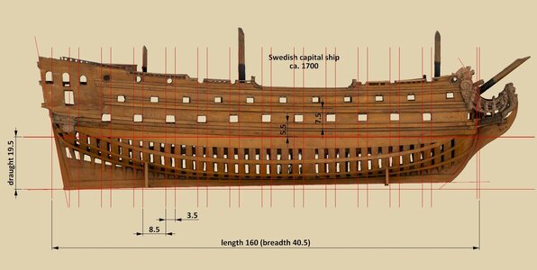
Taking into account the most relevant dimensional considerations, the specifications of the Ö 6 model (enlarged 33 times) were tentatively settled as follows:

Length between posts: 160 feet
Breadth (without planking): 40.5 feet
Draught: 19.5 feet
Distance of gun ports from the waterline: 5.5 feet
Height of lower battery deck: 7.5 feet
Width of gun ports (on lower battery deck): 3.5 feet
Distance between gun ports (on lower battery deck): 8.5 feet

ViewCapture20240505_164751.jpg

The dimensions associated with the gun ports are appropriate for the largest system calibre in the Swedish fleet, at 36 pounds. Guns of this calibre were reserved for ships of the highest rates, as were four gun ports aft (as opposed to only two for ships of lower ranks). To the total number of gun ports should be added at least one gun port on each of the two battery decks, which on the presentation model apparently had to give way to the intended stern decorations (on this, see also the plan reproduced below). On the actual ship, it is also very likely that there were other additional guns on the highest decks that were not reflected in the model, of the smallest calibres and hardly of any tactical significance in the battle fleet.

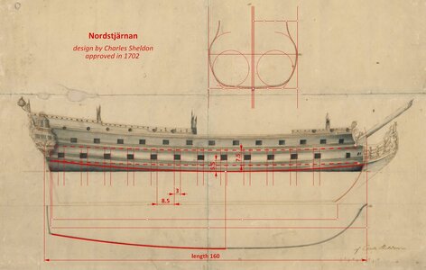
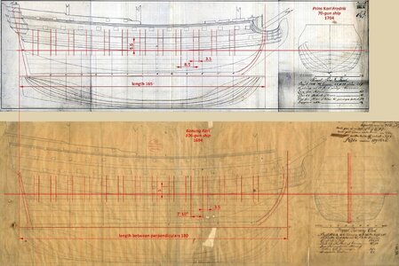
As a kind of parallel, and for a comparison of some dimensions, crucial for determining the size of the ship represented by the Ö 6 model, a ship design from the same period is included below (Swedish archives):


ViewCapture20240505_174133.jpg


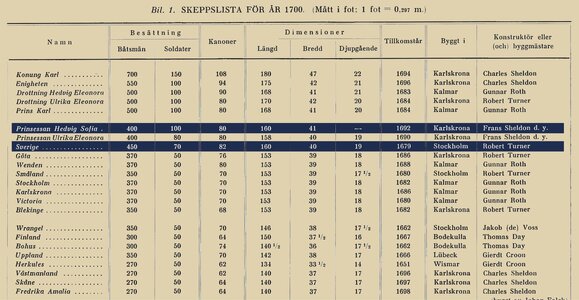
Such characteristics of the Ö 6 model are most consistent with the rate and dimensions of two ships – Sverige 1679 and Prinsessan Hedvig Sofia 1692, as shown in the table below taken from Svenska Flottans Historia. II. 1680-1814, s. 546:


Skeppslista 1700.jpg

.​
 
.​

Before proceeding further, let us stay with the dimensions and scale of the Ö 6 model, or rather the size of the actual ship that this model represents. While it is true that one can search in vain in the archives for plans of Swedish ships from before 1700 for reference, however, invaluable Martes found in the Russian archives a plan of yet another vessel from this very period of activity of the same generation of shipwrights – Prins Karl Fredrik 1704 – which is particularly relevant to this case.

It is reproduced here together with the plan of Konung Karl 1694 (Swedish archives). Both ships were designed by Charles Sheldon (as was Nordstjärnan 1703, shown above), and both plans were already drawn retrospectively, even several years after the vessels were built, most likely by the same person. Despite that, the ships were many decades in active service and it can be thought that these later plans nevertheless represent their characteristics quite faithfully.

As can be seen, the parameters of the gun ports of the Prins Karl Fredrik 1704 perfectly match their dimensions on the Ö 6 model scaled earlier mainly on this basis, whereas in the Konung Karl 1694, while of the same width, they are more tightly spaced due to the need to pack as many as over 100 guns on this vessel. Paradoxically, it was Konung Karl 1694 that was the ship armed with the heaviest, 36-pounder guns, while the others shown here had to practically make do with 24-pounder guns (see on this detailed data in Lars O. Berg, Karolinsk flotta. Studier och tabeller, [in:] Forum Navale 25/1970).


ViewCapture20240506_134528.jpg

.​
 
Last edited:
.​

Prearrangements

The noted distortions of the model are quite minimal, so the only prior correction to its shape was to slightly bend the hull sideways so that the sternpost was exactly in the axis of symmetry. In addition, for further shape testing, the hull was rotated to an even keel – after numerous fittings and preliminary measurements, this seems to be the most promising orientation.

The next step is to obtain the undisturbed outer contours of the frames by virtually 'stripping' the wales and any planking from the full height of the hull. To this end, cross sections were taken off the hull at 'strategic' locations, as shown in the attached images.


ViewCapture20240513_153527.jpg

ViewCapture20240513_153615.jpg

ViewCapture20240513_153640.jpg

ViewCapture20240513_153702.jpg

.​
 
.​

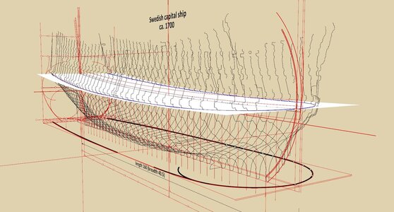
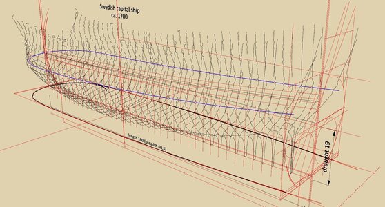
Actually, it was not my original intention to show the rather chaotic-looking working graphics, however, the Ö 6 model scan is revealing more and more of its secrets, and as a sort of curiosity I am demonstrating how the design shape of the line of the greatest breadth was found on the plan view.

To do this, the contours of all the frames were cut by a curved plane at the height of the line of the greatest breadth (found earlier), and then the intersection points were connected by a line (in blue). When this line was projected onto the plan view (thin red line), it was further set back in a parallel manner by the thickness of the planking at the corresponding height of the hull.

It appears that, taking into account the minor distortions of the model, it is possible to perfectly match for the fore part of the hull two types of curves: the combined curve of two circular arcs, commonly used until then by English designers (employed in Sweden at the time), and the logarithmic curve, known and used in turn for a long time already by continental designers, incidentally more flexible and more convenient in design terms. Both of them are shown on either side of the keel as thick black lines. In such a case, the choice of either of these two types of curve would necessarily have to be entirely arbitrary, were it not for the surviving designs of Swedish ships of the period indicating the first variant, that is, a curve combined from two arcs of circles.

For the aft half of the hull, the shape of the line of the greatest breadth is a perfect arc of a circle.


ViewCapture20240517_183816.jpg


ViewCapture20240517_183933.jpg

.​
 
.​

It would actually be appropriate to revisit this interesting case, especially from the perspective of aficionados of ship design à la anglaise, as this model of a Swedish ship reveals a hitherto unknown and undescribed sub-variant of English design, and, importantly, confirmed by its actual use in yet another design of an English ship from the last decades of the 17th century.

Perhaps someone has an idea where else the results of this research can be presented? However, I am keen that this other venue should not be overly niche or elitist, intended only for a very narrow potential readership.

.​
 
Hej Waldemar!

I think that if you want to reach the largest audience of people who are currently working in the field of historical English (or northern European) ship design, the best venue might be Mariners Mirror, which has a wide readership in both the academic and non-specialist worlds and has traditionally covered this area. Your work is certainly of the level of quality for that well-established journal, and it would come to international academic attention. If you want to reach a modelling audience, this kind of forum has more international reach than any of the print publications.

I am afraid that the specifics of wooden ship design methodology is a niche subject in any case; you are probably talking about a few hundred people worldwide who have the necessary interest and background knowledge to grasp the full nuance of what you are discovering, and I suspect a fair proportion of them are already involved in this conversation or at least read this forum. I know several others, who are not modellers, who would be very interested.

However, publishing in a journal such as MM will bring your work to the attention of a wide range of people who are interested in the results and implications of detail changes in design methodology, and who would benefit from a clear explanation of what those changes mean.

An alternative would be to talk to Seaforth, who publish a series of books on design evolution of specific ship types in this period. They look more broadly than just the design methods, but their editor is very knowledgeable and, at the same time, insistent that their books be accessible to the widest possible audience. I would be willing to arrange an introduction. We are doing a book with them on all of the ships of the sailing Swedish navy (we might be interested in incorporating some of your work in that as well).

Fred
 
Another option to consider is working with our museum in a project format to do your kind of reconstructions on a number of models. We often collaborate with outside researchers on projects like that, if the money can be found. You could get better access to the collections so that you can be sure of measurements and perhaps assist in determining which models would benefit most from scanning and analysis. No promises, since it is not my part of the museum, but it might be an idea worth pitching to the collections department.

Fred
 
OH BOY ANOTHER MASTERPIECE O OF RESEARCH, TO FRED I THINK THEREN CDOULD BE QUITE A FEW PEOPLE INTERESWTED IN THIS TYPE OF REASEARCH IE BOOKS BY LAVERY AND GODWIN I HAVE AN IDEA TO BRINGMORE PEOPLE INTERESTED I WILL PM WALDAMERE LATTER NEED TO GET MY IDEAS STRAIGHTM IN MY HEAD( PROBLEM?) THE OTHE4R ARTICAL ONM THE SOS SEEMS TO HAVE ATTRACTED SOME ATTENTION PAUL FOR ONE (DOC LATNER) MAYBE A PM FOR HIS IDEAS. GOD BLESS STAY SAFE ALL DON
 
.​

Thank you very much, Fred, for responding to my appeal. And what a way too!

I am therefore putting the planned presentation on hold until things possibly work out. If only to present the original material to publishers who require it. We'll see how things turn out. Great! Thank you.

.​
 
.​

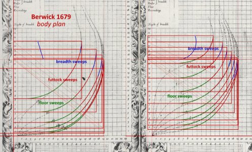
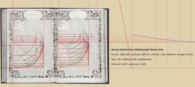
The ship, embodied in a reduced scale as model Ö 6, was designed using an identical conceptual method to the English ship Berwick 1679. It appears to be an unknown method today, that is, at least, not described in modern studies.

It differs from the classic English method, which is widely known and described today, in that here an otherwise simple way of obtaining futtock sweeps of variable radii (as opposed to futtock sweeps of fixed radii) has been found and applied, to the benefit of the harmoniousness of the hull shape, but at the cost of a somewhat more difficult application, as requiring greater proficiency and precision in tracing the lines.

The diagrams below show the essence of this method using example of the body plan of the English capital ship Berwick 1679, reproduced in Deane's Doctrine of Naval architecture, 1670 by Brian Lavery.

In short, each individual bend is framed by its own rectangle, with the width of the corresponding half-breadth and the height of the corresponding distance between the line of the floor and the line of the breadth. In the first step, floor sweeps, breadth sweeps and the diagonal line were drawn (see diagram). In the next step, the futtock sweeps were drawn tangentially to both of the previous sweeps in such a way that they passed through the intersection of the floor sweep and the diagonal line. That's it, except that, naturally, hollowing/bottom curves still had to be added at the very end of the process, connecting the hull body proper to the keel assembly.

It may be further clarified here that in both of these designs, that is, of both Berwick 1679 and Ö 6 model, the variable radius was used typically for (lower) breadth sweeps, while the fixed radius was used for floor sweeps. The latter feature becomes increasingly common in this period, almost completely displacing floor sweeps sporting variable radii, which would return only a few decades later in English design practice (see commentary on this by Mungo Murray in A Treatise on Ship-Building and Navigation, 1754, as well as quite a number of 17th century and later 18th century designs, the latter notably by John Williams.


ViewCapture20241007_130511.jpg

Close up:

ViewCapture20241007_131605.jpg


The conceptual essence of the Ö 6 model has thus been found and presented, but I am no longer sure that I will be able to bring this extremely complicated and arduous process of analysing the whole geometrical construction of the Ö 6 model to a conclusion, when my main reward for the presentations is repeated onslaughts from authors of publications, apparently orthodox and even, one might say, increasingly anachronistic in these matters.

.​
 
Back
Top