US Brig Syren 1803 Model Shipways MS 2260

Joined
Aug 16, 2019
Messages
870
Points
343

US Brig Syren 1803 Model Shipways MS 2260

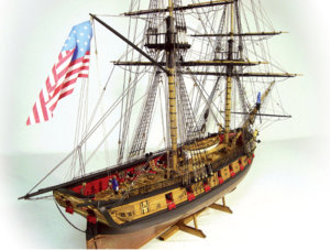
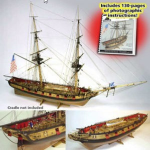
The US brig Syren was a 240 ton Brig build in 1803 in Philadelphia and was capture during the war on 1812-1814 by the British.
I was following the build of the prototype by Chuck Passaro and as soon as the kit was available got it in 2008 I think
I have never see more complete instruction for a kit my only problem it is a Imperial kit and I am a metric guy but I will manage
I will build her stock without any add on
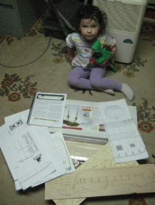
With the help of my partner (He we have to start them young)
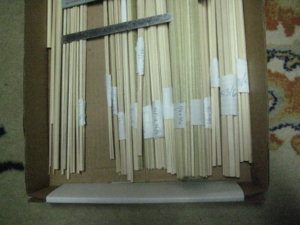
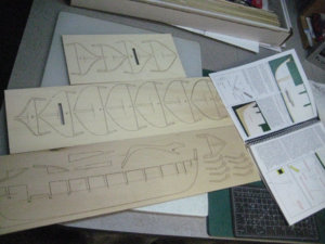
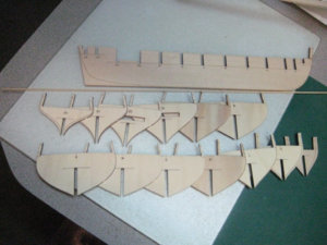
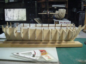
First thing I did was inventory of the kit and identification of all the wood and tag each type.
Will not really start it now as I have to finish my Bireme and the Royal Louis and have to wait for a friend that will build his later this autumn.
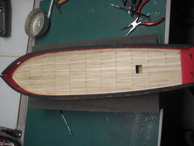
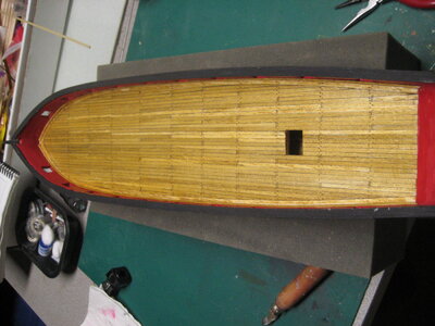
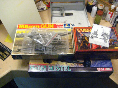
3.jpg4.jpg1.JPG2.JPG
 
It is looking like an interesting kit model - so we will wait, until you and your young pretty assistant will start with modeling :cool:
 
Hi Charles. I've been working on Syren for about two years now and am up to the point where the standing rigging is almost finished, yards and running rigging next. I still have not solved the issue of the "cradle". Have you given any thought on how you'll mount her when finished?

Here's my build log: https://shipsofscale.com/sosforums/threads/build-log-syren-by-passaro.3726/

Yes an no
I like the cradle of my ship to be as discreet as possible
The ship must be the star not the cradle same as my diorama when I made one it is the subject not the envelope that is predominant
 
Chapter 1
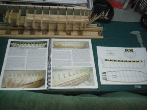
Syren is not my first kit I do, and since I have the kit (2008) I must have read the instructions and look at the plans more than 100 times and I must admit that the instructions are remarkable and the detail never seen by me so far.
There are 20 chapters well detailed with photo to build this ship the instruction booklet is 130 pages abundantly illustrated with photo and sketch
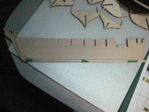
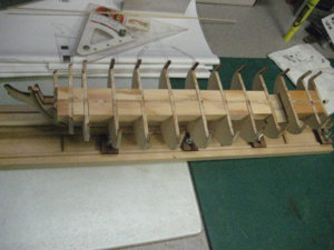
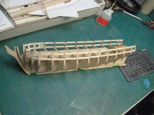
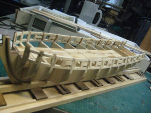
So here is chapter 1 which is the construction of the main structure of the model with the addition and this is a first for me the laying of a bearding line which for all the models that I have done so far was never mentioned.
The bearding line is already dotted on one side of the form and at the other side they let the laser perforate at a certain interval which makes it easy to make both sides symmetrically.
1a.JPG
1b.JPG
1c.JPG
1d.JPG
 
Chapter 2
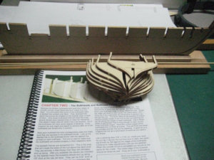
Construction of the frame
3a.JPG
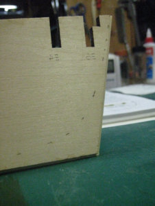
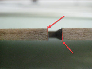
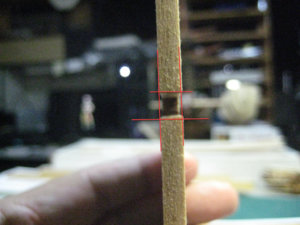
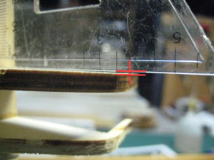
Having already found this in the pass I made sure that the laser cut was well perpendicular to the sections and yes the cutting head was a little out of phase it is minimal but when we add the section at the end the offset is consistent over a distance of 55mm I got 1.5mm of distortion.
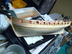
3b.JPG
3ba.JPG
3c.JPG

With a bit of sanding the whole thing was correct.
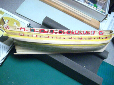
3d.JPG
Here it is chapter 2 to finish
3e.JPG
 
Step 4 Constructions of guns ports and bridge water sweep port

4 1.JPG

The guns ports are 15/32 '' or 11.5mm
The sweep port are 1/8 '' or 3mm
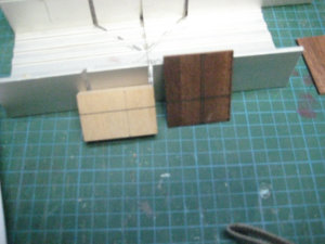
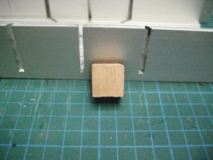
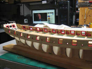
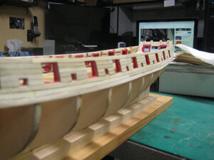
For practical reasons I decide to build 2 templates that will be used at this time to help the placement of the opening and later when hull planking a rim of 1/32 '' or 0.5mm must be allocated my template has this rim which should make my work easier later

4 2.JPG
4 3.JPG
4 4.JPG

Upper and lower limit completed

4 5.JPG

Using templates for placement of the support

4 6.JPG
4 7.JPG

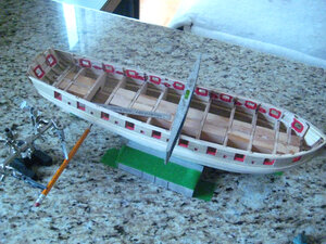
Step 4 complete
4 8.JPG

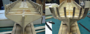
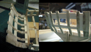
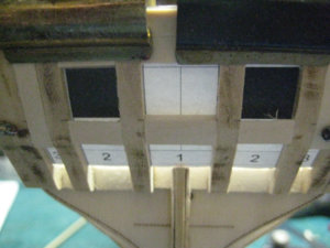
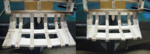
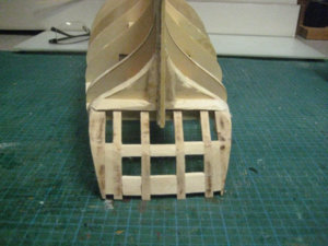
Step 5 the stern structure that should complete the skeleton of the model
 
Chapter 4 building the structure of the stern

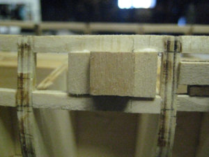
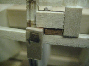
Laying brackets noted that the fact that the 90dg laser cut is not perfect particular care must be taken to ensure that the parts are properly placed.
1.JPG

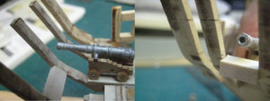
Construct 1 of the 12lb guns for proper placement of the back gun port.
2.JPG

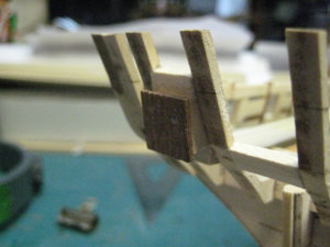
Using my template, place the top bracket.
3.JPG

Here is the structure is made.
4.JPG

Check with the template everything fits perfectly.
5.JPG

Cutting edges for future hull planking
6.JPG

That's it.
7.JPG
And very satisfied so far with instructions that are precise and impeccable
 
That's what I liked the most of this kit. The practicum is included at no charge and it's extremely detailed.
 
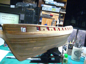
Chapter five hull planking
First the wale plank and the first row of hull plank, the gun port and sweep port are cut
6 1.JPG6 2.JPG

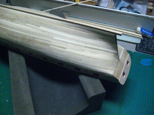
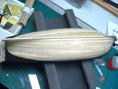
Complete the hull planking
6 3.JPG

Trace the water line at this step
6 4.JPG

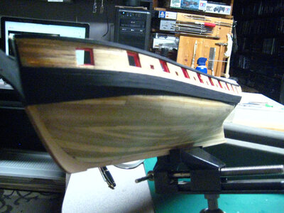
Varnish the section of the hull that will not paint or covert with copper
6 5.JPG6 9.JPG

That complete Chapter 5
 
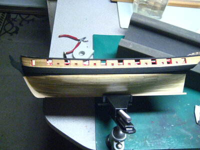
At the step 5 I forget to paint the wales and the section up to the water line black

Now done also put 2 coat of plastic floor on the hull bellow the water line the reason for that is to give a better adherence to the sticky copper plate they will adherers better on a plastic surface, did not have good experience with on wood

1.JPG2.JPG3.JPG4.JPG

Now will begin step 6
 
Chapter six

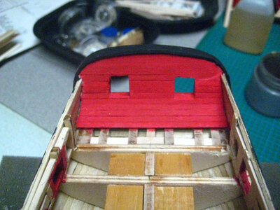
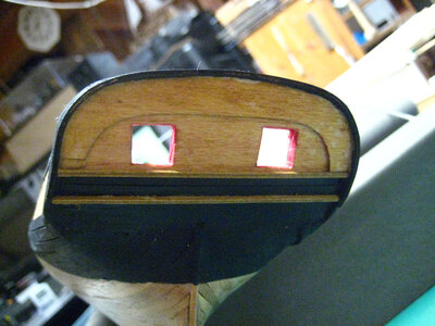
Construction of the stern

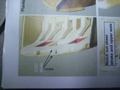
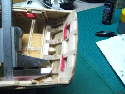
The wall should be reduced from 6mm (¼ ’’) to 2.2mm (3/32 ’’) ideally

p8-1.JPG

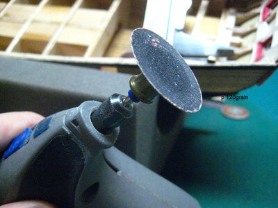
To do this, I use my 120 grit wheel to thin the inner part

p8-2.JPG
p8-3.JPG

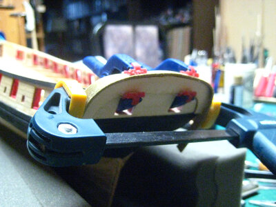
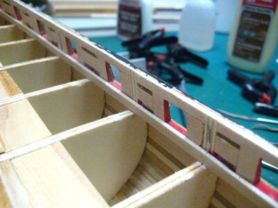
Install the cap rail

p8-4.JPG

Here it is finish with the 2 horizontal mouldings strip install
Looking at the photo I see that I will have to do a little touch-up of paint on the moulding strip that I added on the cap rail (not really visible)

p8-5.JPG
p8-6.JPG

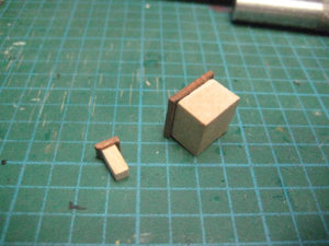
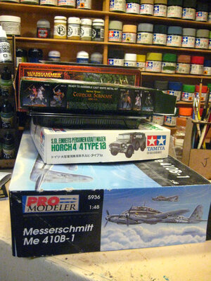
Before starting chapter seven I will do 4 small other project

p8 7.JPG
 
Chapter 7

Okay first, fix my blunder I made at the stern.
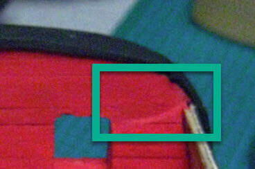
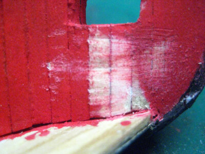
2020-10-28_07-46-39.jpg
1.JPG

Here it is correct
2.JPG

Edge of the wall
3.JPG4.JPG

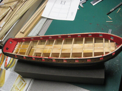
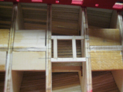
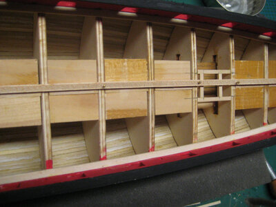
The frame of the staircase and installation and a blank to center the bridge
5.JPG
6 a.JPG

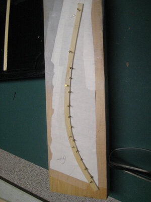
Trace the curve of the rail cap on a sheet and form finalize and install.
6.JPG


The bridge is finished and varnished
7.JPG
8.JPG


Next step chapter 8 the copper plating of the hull

But before this
9.JPG
 
Chapter 7

Okay first, fix my blunder I made at the stern.
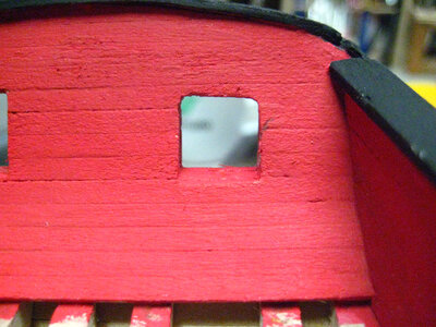
View attachment 199701
View attachment 199702

Here it is correct
View attachment 199703

Edge of the wall
View attachment 199704View attachment 199705

The frame of the staircase and installation and a blank to center the bridge
View attachment 199706
View attachment 199707

Trace the curve of the rail cap on a sheet and form finalize and install.
View attachment 199708


The bridge is finished and varnished
View attachment 199709
View attachment 199710


Next step chapter 8 the copper plating of the hull

But before this
View attachment 199711
Seems, that you are eveyr time making some plastic modeling in between - why not showing us also some of these?
We have a special area of models which are not ship or naval
 
Back
Top